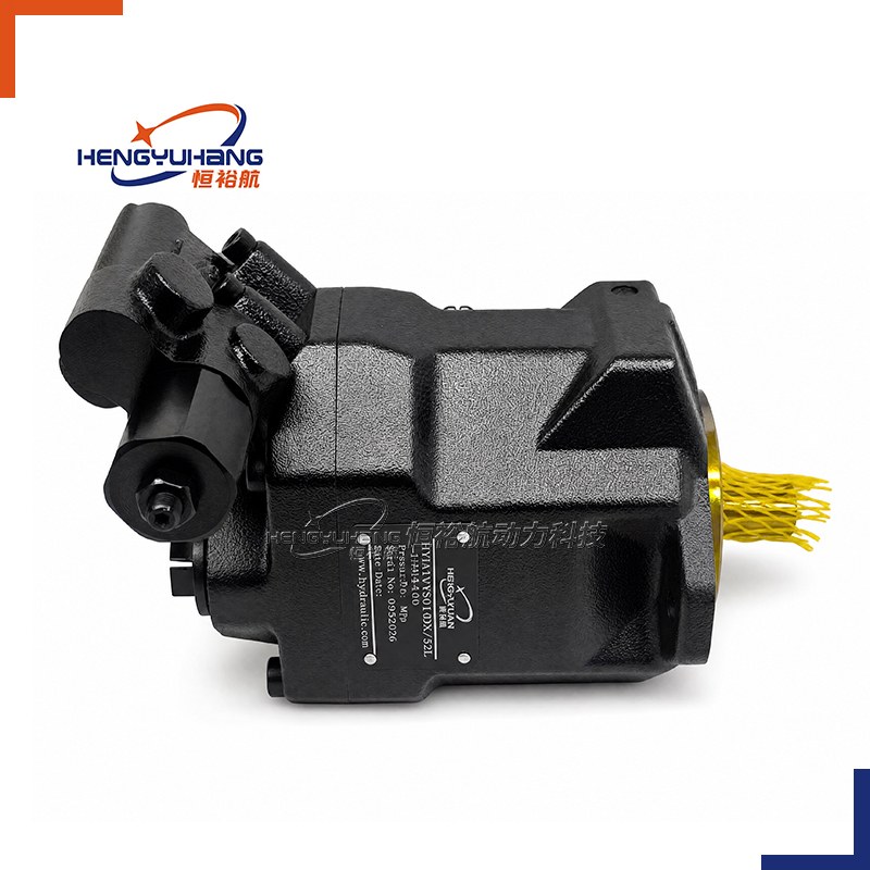
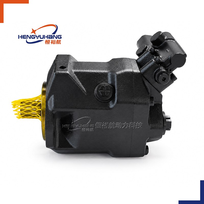
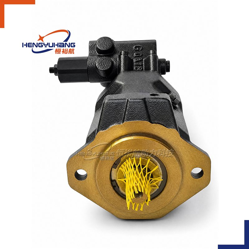
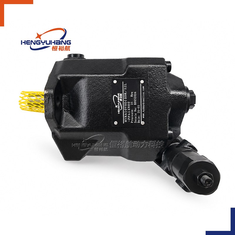
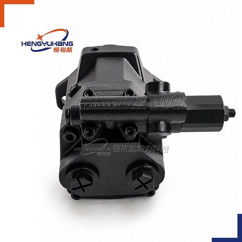
Piston pump
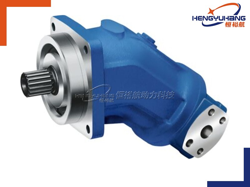
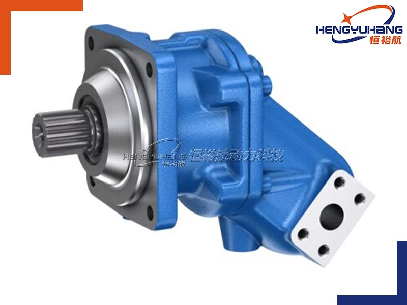
HENGYUHANG Axial Piston Variable Displacement Pump HYHA10VSO10 Series 52
Engineered with an optimized swashplate axial piston rotary group for open-circuit hydrostatic drive systems, the HENGYUHANG HYHA10VSO10 Series 52 variable pump delivers steplessly adjustable hydraulic flow, low operating noise, excellent suction characteristics, and high volumetric efficiency with a nominal continuous pressure of 250 bar and maximum peak pressure of 315 bar (4,550 psi / 31.5 MPa).
| Applications
Designed specifically for medium-pressure industrial machinery, machine tool hydraulic power units, plastic injection secondary circuits, automated clamping systems, and specialized mobile hydraulic packs, this compact variable pump features standardized ISO 3019-1 (SAE 2-bolt) and ISO 3019-2 (Metric 2-bolt) mounting flanges, versatile drive shafts, and comprehensive hydraulic controls (DR, DRG, DFR, DFR1), delivering direct 1:1 OEM drop-in interchangeability for Bosch Rexroth A10VSO 10 Series 52 pumps.
| Key Technical Specifications
Product Model: Hengyuhang Axial Piston Variable Displacement Pump HYHA10VSO10 Series 52
Brand Replacement: Bosch Rexroth A10VSO 10 Series 52 (Size 10) OEM or as requested.
Displacement: 10.5 cm³/rev (0.64 in³/rev) standardized displacement (Size 10)
Rotation Direction: Clockwise (R), counter-clockwise (L) (viewed from drive shaft end)
Speed Range: Nominal rated speed 3,600 r/min (maximum permissible intermittent speed up to 4,320 r/min at reduced displacement)
Peak Pressure: Nominal continuous working pressure 250 bar (3,600 psi); Maximum peak pressure 315 bar (4,550 psi / 31.5 MPa)
- Description
- Tecspecs
- Brand & Reference
- Download HENGYUHANG HYHA10VSO Axial Piston Variable Displacement Pump PDF
- Send an Inquiry
| Overview of HENGYUHANG HYHA10VSO10 Series 52
The HENGYUHANG HYHA10VSO10 Series 52 is a precision-engineered, medium-pressure axial piston variable displacement pump designed specifically for open-circuit hydrostatic drives. Featuring a nominal displacement of 10.5 cm³/rev (0.64 in³/rev), the pump generates a flow rate that is directly proportional to drive speed and internal swashplate angle, allowing infinitely variable volume control from maximum delivery down to near-zero standby stroke. Built with high-strength ductile cast iron housing components, hydrostatically balanced slipper-pad assemblies, and micro-finished valve plate surfaces, the HYHA10VSO10 Series 52 achieves exceptional volumetric efficiency (>92%), rapid dynamic control response, and extended service life under intensive industrial duty cycles.
Engineered with stable shaft bearings, an exceptionally low acoustic signature, and an advantageous power-to-weight ratio (approx. 8 kg total mass), Series 52 serves as the industry standard for compact industrial power units and test benches. The pump offers full mechanical and hydraulic interchangeability with the Bosch Rexroth A10VSO 10 Series 52 family, providing both ISO 3019-1 (SAE 2-bolt, Flange C) and ISO 3019-2 (Metric 2-bolt, Flange A) mounting configurations, standard splined (ANSI B92.1a) and parallel keyed drive shafts (DIN 6885 / ISO 3019-1), and rear-ported metric or SAE threaded working connections. Dual case drain ports (L, L1) ensure flexible mounting orientations, while versatile control options (DR constant pressure, DRG remote pilot control, and DFR/DFR1 load-sensing flow matching) deliver optimized energy conservation across variable load demands.
| Dimension of HENGYUHANG HYHA10VSO10 Series 52
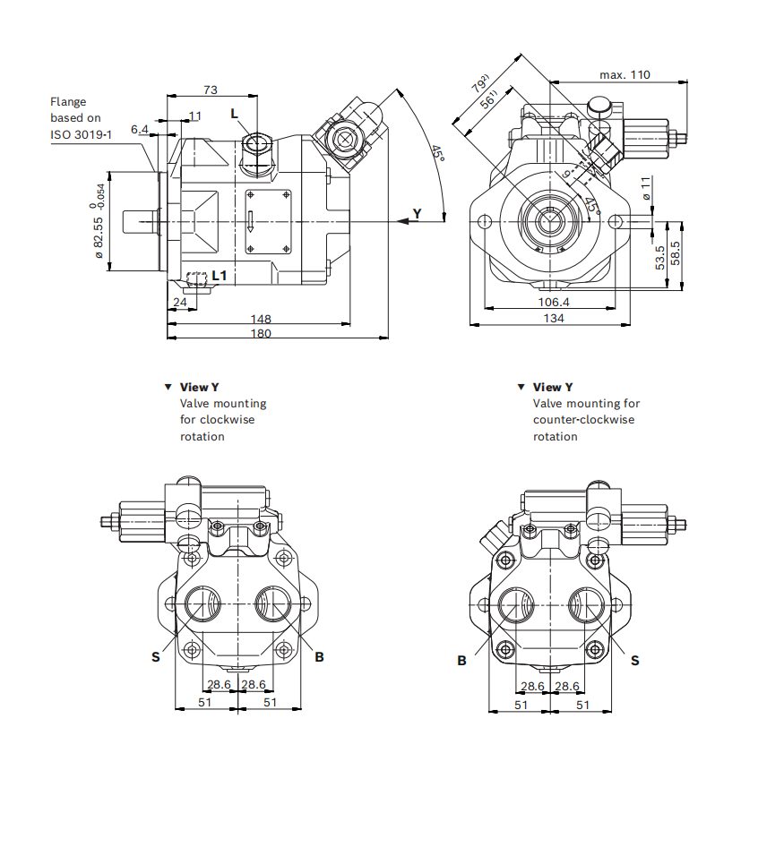
| Interface Data Needed with the Drawing (Size 10)
| Interface Parameter | Metric Version (Flange A / Port Plate 14) | SAE Version (Flange C / Port Plate 64) | Engineering Verification & Assembly Notes |
|---|---|---|---|
| Mounting Flange Standard | ISO 3019-2 2-hole metric oval flange | ISO 3019-1 (SAE A 82-2) 2-hole flange | Pilot spigot Ø 80 mm vs Ø 82.55 mm; 2-bolt clamping |
| Pilot Spigot Diameter | Ø 80 mm (-0.046 mm/0) | Ø 82.55 mm (-0.054 mm/0) | Machine bell-housing bore centering tolerance |
| Flange Bolt Hole Spacing | 109.0 mm center-to-center distance | 106.4 mm center-to-center distance | Symmetrical 2-bolt pattern |
| Flange Bolt Hole Diameter | 2 × Ø 11.0 mm through-holes | 2 × Ø 11.0 mm through-holes | Suitable for M10 / 3/8 in mounting hardware |
| Drive Shaft Option 1 (Splined) | Splined S: 3/4 in (19-4, ISO 3019-1) 11T 16/32 DP | Splined S: 3/4 in (19-4, ISO 3019-1) 11T 16/32 DP | Involute spline ANSI B92.1a, 30° pressure angle, flat root |
| Drive Shaft Option 2 (Splined Reduced) | Splined U: 5/8 in (16-4, ISO 3019-1) 9T 16/32 DP | Splined U: 5/8 in (16-4, ISO 3019-1) 9T 16/32 DP | Involute spline ANSI B92.1a, 30° pressure angle, flat root |
| Drive Shaft Option 3 (Keyed Metric) | Keyed P: Ø 18 mm (DIN 6885 A6×6×25) | — | Parallel keyed shaft with DIN 332 R3.15 × 6.7 centering thread |
| Drive Shaft Option 4 (Keyed SAE) | — | Keyed K: Ø 19.05 mm (3/4 in, ISO 3019-1 19-1) | Parallel keyed shaft (key width 4.76 mm) with centering thread |
| Working Port B (Outlet / Pressure) | DIN 3852: M27 × 2 (thread depth 16 mm) | ISO 11926: 1 1/16-12 UNF-2B (depth 20 mm) | Maximum continuous working pressure 315 bar (4,550 psi) |
| Suction Port S (Inlet) | DIN 3852: M27 × 2 (thread depth 16 mm) | ISO 11926: 1 1/16-12 UNF-2B (depth 20 mm) | Maximum permissible inlet pressure 5 bar (75 psi) |
| Case Drain Ports L, L1 | DIN 3852: M16 × 1.5 (thread depth 12 mm) | ISO 11926: 9/16-18 UNF-2B (depth 12 mm) | Optional M16 × 1.5 adapter; maximum case pressure 2 bar |
| Pilot Pressure Port X | DIN 3852: M14 × 1.5 (with adapter, depth 12 mm) | ISO 11926: 7/16-20 UNF-2B (or M14 × 1.5 with adapter) | Control pressure port for DFR, DFR1, and DRG controllers |
| Overall Pump Length | Approx. 180 mm (mounting face to rear port surface) | Approx. 180 mm (mounting face to rear port surface) | Compact longitudinal envelope |
| Width Across Control Valve | Max. 110 mm (valve center to body envelope) | Max. 110 mm (valve center to body envelope) | Asymmetrical valve mounting depending on rotation (R vs L) |
| Tightening Torques | Flange bolts: 70 N·m; Port B plug: 140 N·m | Flange bolts: 70 N·m; Port B plug: 140 N·m | Ensure calibrated torque wrench application |
| Pump Installation Specifications HENGYUHANG HYHA10VSO10 Series 52
| Comprehensive Ordering Code Structure (Aligned with RE 92713 Series 52)
Code structure — reference: HYHA10VS−O−10/52−Control−Rotation−Seals−Shaft−Flange−Port−ThroughDrive
| Position | Code Element | Specification Options | Description & Functional Details |
|---|---|---|---|
| 01 | Axial Piston Unit | HYHA10VS | Swashplate axial piston variable displacement pump, nominal pressure 250 bar, maximum pressure 315 bar |
| 02 | Operating Mode | O | Pump for open-circuit hydrostatic transmission systems |
| 03 | Displacement Size | 10 | Geometric displacement rating: 10.5 cm³/rev (0.64 in³/rev) |
| 04 | Control Device | DR; DRG; DFR; DFR1 | DR = Hydraulic pressure controller (setting range 50 to 250 bar, standard 250 bar); DRG = Remote-controlled hydraulic pressure controller with remote pressure cut-off; DFR = Pressure and flow controller (load-sensing, differential orifice X-T line open); DFR1 = Pressure and flow controller (load-sensing, X-T line plugged, with flushing function) |
| 05 | Series | 52 | Series 5, Index 2 (Baureihe 52) |
| 06 | Direction of Rotation | R; L | R = Clockwise rotation (viewed on drive shaft); L = Counter-clockwise rotation (viewed on drive shaft) |
| 07 | Sealing Material | V | FKM (fluorocarbon rubber / Viton), compatible with mineral oil HLP DIN 51524 |
| 08 | Drive Shaft | S; U; P; K | S = Involute splined shaft 3/4 in (19-4, ISO 3019-1) 11T 16/32 DP (standard shaft); U = Involute splined shaft 5/8 in (16-4, ISO 3019-1) 9T 16/32 DP (reduced diameter); P = Parallel cylindrical keyed shaft Ø 18 mm (DIN 6885 A6×6×25); K = Parallel cylindrical keyed shaft Ø 19.05 mm (3/4 in, ISO 3019-1 19-1) |
| 09 | Mounting Flange | A; C | A = Metric 2-hole flange based on ISO 3019-2 (pilot Ø 80 mm, bolt spacing 109 mm); C = SAE 2-hole flange based on ISO 3019-1 (pilot Ø 82.55 mm, bolt spacing 106.4 mm) |
| 10 | Working Line Ports | 14; 64 | 14 = Threaded metric ports rear: B & S M27 × 2, L & L1 M16 × 1.5, X M14 × 1.5 (with Flange A); 64 = Threaded UNC ports rear: B & S 1 1/16-12 UNF, L & L1 9/16-18 UNF, X 7/16-20 UNF (with Flange C) |
| 11 | Through Drive | N00 | Standard compact rear cover without auxiliary through-drive |
| Reading Your Replacement Code
| Target Bosch Rexroth Part Code | HENGYUHANG Replacement Code | Direct Interchange Verification Notes |
|---|---|---|
| A10VSO 10 DR / 52R-VSC64N00 | HYHA10VSO-10-DR/52-R-V-S-C-64-N00 | Direct 1:1 drop-in: Size 10, DR pressure controller (250 bar), clockwise, FKM seals, 3/4" 11T splined shaft S, SAE flange C, UNC ports 64, without through-drive |
| A10VSO 10 DFR1 / 52R-VPA14N00 | HYHA10VSO-10-DFR1/52-R-V-P-A-14-N00 | Direct 1:1 drop-in: Size 10, DFR1 load-sensing control with flushing, clockwise, FKM seals, keyed shaft P (Ø18 mm), metric flange A (Ø80 mm), metric ports 14 |
| A10VSO 10 DFR / 52R-VSC64N00 | HYHA10VSO-10-DFR/52-R-V-S-C-64-N00 | Direct 1:1 drop-in: Size 10, DFR load-sensing control, clockwise, FKM seals, splined shaft S, SAE flange C, UNC ports 64, without through-drive |
| A10VSO 10 DRG / 52R-VPA14N00 | HYHA10VSO-10-DRG/52-R-V-P-A-14-N00 | Direct 1:1 drop-in: Size 10, DRG remote pressure control, clockwise, FKM seals, keyed shaft P (Ø18 mm), metric flange A, metric ports 14 |
| A10VSO 10 DR / 52L-VUC64N00 | HYHA10VSO-10-DR/52-L-V-U-C-64-N00 | Direct 1:1 drop-in: Size 10, DR pressure control, counter-clockwise rotation, FKM seals, reduced splined shaft U (5/8" 9T), SAE flange C, UNC ports 64 |
| A10VSO 10 DFR1 / 52R-VKA14N00 | HYHA10VSO-10-DFR1/52-R-V-K-A-14-N00 | Direct 1:1 drop-in: Size 10, DFR1 load-sensing control, clockwise, FKM seals, keyed shaft K (3/4 in ISO 3019-1), metric flange A, metric ports 14 |
| Techspecs of HENGYUHANG HYHA10VSO10 Series 52
| 4.1 Standard Unit Technical Data (Size 10, Aligned with RE 92713)
| Parameter / Technical Specification | Symbol | Metric Unit | US Imperial Unit | Engineering Value & Operating Limits |
|---|---|---|---|---|
| Nominal Displacement per Revolution | Vg max | cm³ | in³ | 10.5 (0.64 in³) |
| Maximum Nominal Speed (at Vg max, p abs ≥ 1.0 bar) | n nom | r/min | rpm | 3,600 |
| Maximum Permissible Intermittent Speed (at Vg < Vg max) | n max perm | r/min | rpm | 4,320 |
| Maximum Flow Delivery (at n nom and Vg max) | qv max | l/min | gpm | 37.0 (9.7 gpm) |
| Flow Delivery at Standard Electric Motor Speed (n = 1500 r/min) | qvE | l/min | gpm | 15.0 (4.0 gpm) |
| Drive Power Delivery (at n nom, Vg max, Δp = 250 bar) | P max | kW | HP | 16.0 (22.0 HP) |
| Drive Power Delivery (at n = 1500 r/min, Δp = 250 bar) | PE | kW | HP | 7.0 (9.4 HP) |
| Drive Torque Delivery (at Vg max, Δp = 250 bar) | M max | N·m | lb-ft | 42.0 (31.0 lb-ft) |
| Drive Torque Delivery (at Vg max, Δp = 100 bar) | M | N·m | lb-ft | 17.0 (13.0 lb-ft) |
| Torsional Shaft Stiffness — Splined Shaft S | c | kN·m/rad | lb-ft/rad | 9.2 (6,760 lb-ft/rad) |
| Torsional Shaft Stiffness — Splined Shaft U | c | kN·m/rad | lb-ft/rad | 6.8 (5,020 lb-ft/rad) |
| Torsional Shaft Stiffness — Keyed Shaft P | c | kN·m/rad | lb-ft/rad | 10.7 (7,892 lb-ft/rad) |
| Torsional Shaft Stiffness — Keyed Shaft K | c | kN·m/rad | lb-ft/rad | 10.8 (7,965 lb-ft/rad) |
| Rotary Group Moment of Inertia | J TW | kg·m² | lb-ft² | 0.0006 (0.0142 lb-ft²) |
| Maximum Angular Acceleration | α | rad/s² | rad/s² | 8,000 |
| Internal Case Fluid Volume | V | l | gal | 0.2 (0.05 gal) |
| Total Pump Weight (Approximate Dry Mass) | m | kg | lbs | 8.0 (17.0 lbs) |
| 4.2 Working Pressure Range & Differential Operating Limits (from RE 92713)
| Pressure Parameter | Symbol | Metric Pressure Rating | US Imperial Rating | Operational Definition & System Boundaries |
|---|---|---|---|---|
| Nominal Working Pressure (Port B) | p nom | 250 bar | 3,600 psi | Maximum continuous operating design pressure |
| Maximum Peak Pressure (Port B) | p max | 315 bar | 4,550 psi | Single event duration ≤ 2.5 ms; cumulative limit 300 operating hours |
| Minimum Pressure (High-Pressure Side B) | pB abs | 10 bar | 145 psi | Minimum required pressure to prevent cavitation and slipper lift |
| Rate of Pressure Change | RA max | 16,000 bar/s | 232,000 psi/s | Maximum permissible rate of pressure build-up or reduction |
| Minimum Suction Pressure (Port S) | pS min | 0.8 bar absolute | 12 psi abs | Minimum inlet pressure required at rated rotational speed and full displacement |
| Maximum Suction Pressure (Port S) | pS max | 5.0 bar absolute | 75 psi abs | Maximum allowable static inlet supercharging pressure |
| Maximum Case Drain Pressure (Port L, L1) | pL max | 2.0 bar absolute | 30 psi abs | Maximum 0.5 bar above inlet port S; unrestricted drain line required |
| 4.3 General Operating Conditions & Fluid Compatibility (Aligned with RE 92713)
| Parameter | Permissible Operating Range | Optimal Target Condition | Engineering Compliance Notes |
|---|---|---|---|
| Hydraulic Fluid Type | Mineral oil HLP according to DIN 51524 | High-grade anti-wear mineral oil | Environmentally acceptable fluids require engineering review |
| Continuous Kinematic Viscosity | ν = 10 to 400 mm²/s (cSt) | ν opt = 16 to 36 mm²/s (cSt) | Measured at case drain outlet temperature |
| Cold Start Maximum Viscosity | ν max ≤ 1600 mm²/s (cSt) | System pre-heating recommended | Limit: t ≤ 3 min, p ≤ 50 bar, n ≤ 1000 rpm |
| Short-Term Minimum Viscosity | ν min = 10 mm²/s (cSt) | Prevent prolonged peak throttling | Permissible during brief peak thermal transients |
| Operating Temperature Range | Standard FKM Seals: -25 °C to +110 °C | +30 °C to +65 °C (+86 °F to +149 °F) | Differential between unit and fluid ≤ 25 K |
| Fluid Cleanliness Requirement | ISO 4406 Class 20/18/15 (NAS 1638 Class 9) | ISO 4406 Class 19/17/14 | Fine absolute filtration (βx ≥ 75) strongly recommended |
Advantages
Optimized Swashplate Volumetric Efficiency
Precision-machined 9-piston rotary group delivers stepless variable displacement with overall operating efficiencies exceeding 92%, substantially reducing machine heat generation.
Low Acoustic Emission Profile
Optimized pre-compression timing on the valve plate and hydrostatically balanced cylinder assemblies minimize hydraulic pressure ripple and airborne machine noise.
Compact Footprint & Favorable Power-to-Weight Ratio
Weighing only 8.0 kg (17 lbs) with a total envelope length of 180 mm, Series 52 delivers 16 kW of hydraulic power in space-constrained industrial power packs.
Versatile Modular Hydraulic Controls
Standardized mounting for DR (pressure limiter, 50–250 bar), DRG (remote pilot relief), and DFR/DFR1 (load-sensing flow control with standby differential throttling).
Dual Mounting Standard Availability
Offers true global compatibility with both ISO 3019-1 (SAE 2-bolt Ø82.55 mm spigot) and ISO 3019-2 (Metric 2-bolt Ø80 mm spigot) mounting flanges.
Direct 1:1 OEM Drop-In Interchangeability
Dimensionally identical to Bosch Rexroth A10VSO 10 Series 52 in mounting face, shaft length, port centerlines, and control valve envelopes, enabling zero-rework replacement.
Reference
Displacement & Control Configuration Matrix
Standard Displacement Available: Size 10 (10.5 cm³/rev, 0.64 in³/rev).
Controller Architectures:
DR Controller: Hydraulic pressure limiter regulating pump output to consumer demand within 50 to 250 bar (standard setting: 250 bar; pressure increase Δp=6 bar, hysteresis ≤4 bar).
DRG Controller: Remote-controlled pressure regulator utilizing a remote pilot relief valve connected to port X for proportional or multi-pressure switching.
DFR / DFR1 Controller: Dynamic load-sensing flow matching with integrated pressure limiter; adjusts pump displacement to match variable orifice demand (DFR1 version includes internal flushing function for responsive low-temperature operation).
Shaft and Port Standards: Splined 3/4" (11T) or 5/8" (9T), parallel keyed Ø18 mm or Ø19.05 mm; rear threaded metric M27 × 2 or SAE 1 1/16-12 UNF connections.
Target Brand Interchangeability Matrix
The HENGYUHANG HYHA10VSO10 Series 52 provides verified 1:1 direct interchangeability across the full Bosch Rexroth A10VSO 10 Series 52 range:
Bosch Rexroth A10VSO 10 DR / 52 → HYHA10VSO-10-DR/52 (Metric Flange A or SAE Flange C)
Bosch Rexroth A10VSO 10 DFR / 52 → HYHA10VSO-10-DFR/52 (Metric Flange A or SAE Flange C)
Bosch Rexroth A10VSO 10 DFR1 / 52 → HYHA10VSO-10-DFR1/52 (Metric Flange A or SAE Flange C)
Bosch Rexroth A10VSO 10 DRG / 52 → HYHA10VSO-10-DRG/52 (Metric Flange A or SAE Flange C)
Brand Replacement
The HENGYUHANG HYHA10VSO10 Series 52 is engineered and manufactured as an exact 1:1 drop-in replacement for the Bosch Rexroth A10VSO 10 Series 52 axial piston variable pump. Every unit is produced to stringent manufacturing tolerances on multi-axis CNC machines and individually calibrated on automated hydraulic test benches to reproduce OEM response time, control curve linearity, pressure cut-off stability, and flow output. Utilizing identical mounting flange dimensions (ISO 3019-1 SAE A or ISO 3019-2 Metric Ø80), standardized shaft centerlines, matching thread ports, and identical control valve configurations, the HYHA10VSO10 Series 52 installs seamlessly into existing equipment without piping alterations, bracket modifications, or electrical re-programming. Maintenance managers, equipment rebuilders, and hydraulic distributors gain an immediate, high-availability replacement solution that maintains original machine performance while optimizing procurement lead times and operating costs.
Applications
Machine Tool Auxiliary Hydraulics: Centralized clamping, tool changer actuation, workpiece positioning, and lubrication power units on CNC lathes and milling centers.
Industrial Automation & Assembly Equipment: Precision hydraulic power units for automated transfer lines, component testing fixtures, and robotic positioning systems.
Plastic & Rubber Auxiliary Machinery: Core-pulling, mold clamping, and auxiliary actuation circuits in compact blow molding and injection systems.
Material Testing & Calibration Benches: Hydrostatic pressure sources for valve test stands, burst pressure testing rigs, and endurance simulation equipment.
Mobile Specialized Hydraulic Packs: Compact auxiliary hydraulic power packs for specialized municipal utility vehicles, aerial access platforms, and maintenance cranes.
Industrial Hydraulic Power Units (HPUs): Energy-efficient variable displacement power supplies for manufacturing plant machinery and compact hydraulic presses.
Package & Shipping
| Packaging Construction | Heavy-duty export fumigation-free wooden case with custom-molded shock-absorbing high-density foam internal cradles |
|---|---|
| Corrosion Protection | Internal test fluid preservation, external anti-rust oil coating, and vapor corrosion inhibitor (VCI) sealed barrier bagging |
| Port & Shaft Protection | Heavy-duty threaded blanking plugs on all working and pilot ports, and precision protective polymer shaft sleeves |
| Package Dimensions | Approx. 340 × 260 × 240 mm (Single pump packaging) |
| Gross Weight | Approx. 10.5 kg (inclusive of packaging materials and protective fixtures) |
| Standard Lead Time | 3 – 5 business days for stocked standard models; 15 – 20 business days for customized batch production |
| Global Shipping Options | Express air courier (DHL / FedEx / UPS / TNT) for critical downtime maintenance; Ocean FCL/LCL and Air Cargo for bulk orders |
| Quality Documentation | Complete factory dynamic test inspection certificate, CE declaration, and customized private-label nameplate available |
Why Choose Hengyuhang?
Direct Factory Precision Manufacturing & CNC Excellence: Manufactured in our state-of-the-art production facility equipped with high-precision 4-axis and 5-axis CNC machining centers, automated cylinder block machining, and micro-finishing rotary grinding equipment (Ra < 0.2 μm) to guarantee tight internal running clearances, low friction, and exceptional volumetric efficiency.
100% Full-Cycle Multi-Parameter Factory Inspection: Every single pump undergoes rigorous automated bench testing before shipment, verifying displacement control accuracy, volumetric efficiency (>92%), nominal and peak pressure stability, case leakage flow, and acoustic noise spectrum. Zero untested units leave the factory.
Seamless 1:1 OEM Drop-In Interchangeability: Dimensionally matched to European, ISO, and SAE standards, providing seamless 1:1 mechanical and hydraulic interchangeability across premier global brands (Bosch Rexroth, Parker, Danfoss, etc.) with zero mounting modifications required.
Flexible Engineering Customization & Rapid Prototyping: Supported by a seasoned fluid power engineering team capable of customizing control valve calibrations, specialized shaft geometries, non-standard port connections, and tailored pressure ranges with rapid prototyping and low MOQ requirements.
Robust Supply Chain, Extensive Inventory & Fast Global Dispatch: Extensive raw material stock of specialized ductile iron castings, precision piston-slipper assemblies, and high-grade seal kits enables rapid assembly and 48–72 hour dispatch for emergency breakdown replacements, supported by complete export logistics.
12-Month Comprehensive Warranty & Lifetime Technical Support: All pumps are backed by a comprehensive 12-month manufacturer warranty against defects in materials and workmanship, supplemented by 24/7 technical engineering consultation, CAD drawing verification, and full lifecycle service assistance.
HENGYUHANG Axial Piston Variable Displacement Pump HYHA10VSO10 Series 52 (Swashplate Design Compact Hydraulic Pump, 10.50 cm³/rev) is a high-precision, open-circuit axial piston variable displacement pump engineered specifically for compact industrial hydraulic power units, mobile machinery auxiliary systems, and automated test rigs requiring ultra-responsive flow control, high operating efficiency, and long service life. Designed as a 100% direct dimensional, hydraulic, and functional custom drop-in replacement for the industry standard Bosch Rexroth A10VSO 10 Series 52 (A10VSO10/52), the HYHA10VSO10 Series 52 features an advanced swashplate rotary group with an infinitely variable displacement of 10.50 cm³/rev (0.64 in³/rev). Operating at a continuous nominal working pressure (p_nom) of 250 bar (3,600 psi / 25 MPa) and peak surge pressures (p_max) up to 315 bar (4,550 psi / 31.5 MPa), this compact power unit delivers continuous flows up to 37.0 L/min at its rated speed of 3600 rpm (15.0 L/min at 1500 rpm) with an exceptionally fast swashplate response time and minimal noise emissions. The pump offers universal interchangeability with both SAE A 2-bolt mounting flanges (ISO 3019-1, centering pilot Ø82.55 mm, 106.4 mm bolt centers) and European metric 2-bolt oval flanges (ISO 3019-2, centering pilot Ø80.0 mm, 109.0 mm bolt centers), multiple drive shaft configurations including ANSI B92.1a involute splines (3/4 in 11T Code S, 5/8 in 9T Code U) and DIN 6885 / ISO parallel keyed shafts (Ø18 mm Code P, Ø19.05 mm Code K), rear metric (M27 × 2) or SAE UNF (1 1/16-12UNF) fluid ports, and a comprehensive suite of modular hydro-mechanical controllers (DR pressure cut-off, DRG remote pressure relief, and DFR/DFR1 load-sensing flow controllers), providing machine builders and maintenance engineers with seamless OEM replacement capability without hydraulic line redesign or bracket modification.
| Applications
The HYHA10VSO10 Series 52 swashplate variable displacement pump is engineered for demanding industrial stationary equipment and mobile hydrostatic auxiliary drives requiring high pressure, compact footprint, and dynamic on-demand flow regulation:
Machine Tools and CNC Machining Centers: Delivers energy-efficient on-demand hydraulic power to automatic workpiece clamping fixtures, dynamic tool changers, spindle chuck actuators, and auxiliary hydraulic tailstocks.
Compact Industrial Hydraulic Power Units (HPUs): Serves as the primary variable displacement pressure source in centralized hydraulic power packs for factory automation, workshop hydraulic presses, and transfer lines.
Plastic Injection Molding and Rubber Presses: Feeds auxiliary core-pulling hydraulic cylinders, mold height adjustment actuators, and pneumatic/hydraulic ejector safety mechanisms with low heat generation.
Commercial Vehicles and Municipal Utility Chassis: Direct-driven via auxiliary PTOs or electric motors; provides proportional hydraulic power to salt spreaders, snow plow blade positioners, and tail-lift platforms.
Automated Hydraulic Test Rigs and Calibration Benches: Provides ultra-smooth, ripple-free pressurized fluid flow for precision valve endurance testing, cylinder leakage verification, and sensor calibration systems.
Mobile Construction and Material Handling Auxiliary Circuits: Powers auxiliary hydraulic functions including cab tilting cylinders, steering booster boosters, hydrostatic fan drive circuits, and secondary brake charging accumulators.
| Key Specifications Overview
| Parameter | Engineering Specification (Series 52 Industrial & Mobile Standard) |
|---|---|
| Series Architecture | Swashplate Design Variable Axial Piston Rotary Group for Open Circuit Hydrostatic Drives (Series 52) |
| Displacement Frame Size (HYHA10VSO) | Nominal Size 10: Maximum Geometric Displacement Vg_max = 10.50 cm³/rev (0.64 in³/rev) |
| Nominal Working Pressure (p_nom) | 250 bar (3,600 psi / 25 MPa) continuous absolute operating pressure at working port B |
| Maximum Peak Operating Pressure (p_max) | 315 bar (4,550 psi / 31.5 MPa) absolute maximum peak pressure (single period max 2.5 ms, cumulative 300 h) |
| Minimum Pressure at Working Port B (p_B abs) | 10 bar (145 psi) absolute minimum pressure required on the high-pressure side to prevent swashplate/shoe damage |
| Maximum Rate of Pressure Change (RA_max) | 16,000 bar/s (232,000 psi/s) maximum permissible rate of pressure rise and reduction across operating range |
| Suction Port Pressure Limits (p_S) | Minimum inlet pressure: 0.8 bar (12 psi) absolute; Maximum permissible inlet pressure: 5.0 bar (75 psi) absolute |
| Case Drain Pressure Limits (p_L max) | Maximum 2.0 bar (30 psi) absolute at ports L / L1 (max 0.5 bar above inlet pressure; external drain line required) |
| Rotational Speed at Full Displacement (Vg_max) | Nominal speed: n_nom = 3600 rpm (at p_abs = 1 bar inlet); Intermittent limiting speed: n_max = 4320 rpm (at Vg < Vg_max) |
| Flow Output Delivery Rating | qv = 37.0 L/min (9.7 gpm) at rated 3600 rpm; qvE = 15.0 L/min (4.0 gpm) at standard electric motor speed 1500 rpm |
| Drive Power Consumption @ 250 bar | P = 16.0 kW (22.0 HP) at 3600 rpm and Δp = 250 bar; PE = 7.0 kW (9.4 HP) at 1500 rpm and Δp = 250 bar |
| Drive Torque Output Requirements | M = 42.0 Nm (31.0 lb-ft) at Δp = 250 bar; M = 17.0 Nm (13.0 lb-ft) at Δp = 100 bar (1450 psi) |
| Drive Shaft Torsional Stiffness (c) | Splined S: 9.2 kNm/rad; Splined U: 6.8 kNm/rad; Parallel Keyed P: 10.7 kNm/rad; Parallel Keyed K: 10.8 kNm/rad |
| Rotary Group Moment of Inertia (JTW) | 0.0006 kg·m² (0.0142 lb-ft²) with maximum permissible angular acceleration α = 8000 rad/s² |
| Mounting Flange Standards | Flange C: ISO 3019-1 (SAE A 2-bolt, pilot Ø82.55 mm) | Flange A: ISO 3019-2 (Metric 2-bolt oval, pilot Ø80.00 mm) |
| Drive Shaft Standards | Splined 3/4 in 11T (Code S), Splined 5/8 in 9T (Code U), Keyed Ø18 mm DIN 6885 (Code P), Keyed 3/4 in ISO (Code K) |
| Hydraulic Service Port Standards | Port Plate 14: Metric DIN 3852 (M27 × 2 rear ports) | Port Plate 64: SAE ISO 11926 (1 1/16-12UNF rear ports) |
| Modular Control Options | DR (Pressure Controller), DRG (Remote Pressure Relief), DFR / DFR1 (Load Sensing Pressure & Flow Controller) |
| Sealing Material & Fluid Temperature Range | Standard FKM (fluorocarbon rubber / Viton) shaft seals; Permissible fluid temperature: -25°C to +115°C |
| Hydraulic Fluid & Cleanliness Standard | Mineral oil HLP DIN 51524 (viscosity 16~36 mm²/s optimal); ISO 4406 Class 20/18/15 (Class 19/17/14 above 90°C) |
| Total Bare Unit Mass | Approximately 8.0 kg (17.6 lbs); Case internal fluid filling volume: 0.20 L (0.05 gal) |
| Technical Performance Matrix Across Operational Speeds
| Model Code | Displacement cm³/rev (in³/rev) | Operating Pressure (bar / psi) | Operating Speed (rpm) | Delivery Flow (L/min / gpm) | Input Power @ 250 bar (kW / HP) | Torque @ 250 bar Nm (lb-ft) | Weight kg (lbs) | ||||
|---|---|---|---|---|---|---|---|---|---|---|---|
| Nominal (p_nom) | Peak (p_max) | Rated (n_nom) | Limit (n_max) | @ 3600 rpm | @ 1500 rpm | @ 3600 rpm | @ 1500 rpm | ||||
| HYHA10VSO 10 / 52 | 10.50 (0.64) | 250 / 3,600 | 315 / 4,550 | 3600 | 4320 | 37.0 (9.7) | 15.0 (4.0) | 16.0 (22.0) | 7.0 (9.4) | 42.0 (31.0) | 8.0 (17.6) |
| Modular Control Devices and Functional Principles
| Controller Code | Control Mechanism | Setting Range & Parameters | Functional Operation & Dynamic Benefit |
|---|---|---|---|
| DR | Hydraulic Pressure Controller (Constant Pressure Cut-Off) | 50 ~ 250 bar (725 ~ 3,600 psi); Standard factory setting: 250 bar | Limits maximum outlet pressure within the control range. When system pressure reaches the preset value, the pump automatically destrokes swashplate angle to maintain constant pressure while delivering only required consumer leakage flow, preventing heat buildup. |
| DRG | Remotely Controlled Pressure Relief Valve Controller | Differential pressure Δp: 14 ~ 22 bar (200 ~ 320 psi); Standard setting: 20 bar (290 psi) | Enables multi-pressure stage regulation or electro-proportional pressure control via an external pilot relief valve piped to port X. Control fluid quantity at port X is approximately 1.5 L/min (0.4 gpm) at 20 bar differential pressure. |
| DFR / DFR1 | Load-Sensing Pressure & Flow Controller (Constant Differential Pressure) | Pressure setting up to 250 bar; Differential pressure Δp: 14 ~ 22 bar; Standard setting: 14 bar (200 psi) | Keeps delivery flow constant regardless of varying load pressure across an external metering orifice. Standby zero-stroke pressure is approximately 1 to 2 bar above set Δp when port X is unloaded to tank. DFR has port X-T open; DFR1 features a plugged X-T port with an internal flushing function. |
| Mounting Flange, Shaft and Port Specifications
| Component Category | Designation Code | Standard Interface Dimensions | Engineering Specifications & Compliance |
|---|---|---|---|
| Mounting Flange Interfaces | Flange C (SAE 2-Bolt) | ISO 3019-1 (SAE A 2-bolt oval); Pilot Ø82.55 mm (0/-0.054 mm); Hole centers: 106.4 mm (4.188 in) | 2 × Ø11.0 mm clearance through holes; pilot depth 6.4 mm; overall length from mounting face to rear end: 180.0 mm (148.0 mm to port centerline). |
| Flange A (Metric 2-Bolt) | ISO 3019-2 (Metric 2-bolt oval); Pilot Ø80.00 mm (0/-0.046 mm); Hole centers: 109.0 mm | 2 × Ø11.0 mm clearance through holes; pilot depth 7.0 mm; overall length from mounting face to rear end: 180.0 mm (148.0 mm to port centerline). | |
| Drive Shaft Configurations | Shaft S (Splined 3/4 in) | ANSI B92.1a 11T 16/32DP (19-4, ISO 3019-1); 30° pressure angle; flat root side fit; tolerance class 5 | Usable spline length: 30.0 mm; total extension from flange face: 38.0 mm; internal end thread: 1/4-20UNC-2B; torsional stiffness c = 9.2 kNm/rad. |
| Shaft U (Splined 5/8 in) | ANSI B92.1a 9T 16/32DP (16-4, ISO 3019-1); 30° pressure angle; flat root side fit; tolerance class 5 | Reduced diameter splined shaft; usable spline length: 22.0 mm; total extension: 31.8 mm; internal end thread: 1/4-20UNC-2B; stiffness c = 6.8 kNm/rad. | |
| Shaft P (Keyed Metric) | DIN 6885 parallel keyed shaft A6 × 6 × 25; shaft diameter Ø18.0 mm (+0.008/-0.003 mm) | Keyed shaft length: 36.0 mm; extension: 28.0 mm; centering thread R3.15 × 6.7 DIN 332; torsional stiffness c = 10.7 kNm/rad. | |
| Shaft K (Keyed Inch) | ISO 3019-1 19-1 parallel keyed shaft; shaft diameter Ø19.05 mm (3/4 in, +0.009/-0.004 mm) | Key width: 4.76 mm (+0.025 mm); shaft length: 41.0 mm; extension: 33.0 mm; centering thread R3.15 × 6.7; torsional stiffness c = 10.8 kNm/rad. | |
| Service & Auxiliary Ports | Port Plate 14 (Metric) | Rear Ports: Working B = M27 × 2 (16 mm deep, 315 bar max); Suction S = M27 × 2 (16 mm deep, 5 bar max) | Case Drain L / L1 = M16 × 1.5 (12 mm deep, 2 bar max); Pilot Port X = M14 × 1.5 (12 mm deep, 315 bar max). Complies with DIN 3852 with profiled sealing ring. |
| Port Plate 64 (SAE UNF) | Rear Ports: Working B = 1 1/16-12UNF-2B (20 mm deep, 315 bar max); Suction S = 1 1/16-12UNF-2B | Case Drain L / L1 = 9/16-18UNF-2B (standard without adapter, 2 bar max) or M16 × 1.5 with adapter; Pilot Port X = 7/16-20UNF-2B (315 bar max) or M14 × 1.5 with adapter. |
| Direct Interchangeability and OEM Replacement Matrix (Rexroth A10VSO 10 Series 52)
| Hengyuhang Series | OEM Target Model | OEM Type Reference Code | Interchangeability and Drop-In Compliance |
|---|---|---|---|
| HYHA10VSO 10 / 52 DR | Bosch Rexroth A10VSO 10 / 52 DR | A10VSO10DR/52R-PPA14N00 | 100% direct drop-in replacement with metric ISO 80-2 flange, DIN 6885 Ø18 mm keyed shaft P, rear M27 × 2 metric ports, and DR constant pressure cut-off controller. |
| HYHA10VSO 10 / 52 DFR1 | Bosch Rexroth A10VSO 10 / 52 DFR1 | A10VSO10DFR1/52R-VSC64N00 | Direct bolt-on replacement with SAE A 2-bolt flange (pilot Ø82.55 mm), ANSI B92.1a 3/4 in 11T splined shaft S, rear 1 1/16-12UNF ports, and load-sensing flow controller. |
| HYHA10VSO 10 / 52 DFR | Bosch Rexroth A10VSO 10 / 52 DFR | A10VSO10DFR/52R-VSC64N00 | Direct replacement for load-sensing open X-T circuits in mobile utility and industrial systems; identical 180 mm casing length and 250 bar nominal pressure. |
| HYHA10VSO 10 / 52 DRG | Bosch Rexroth A10VSO 10 / 52 DRG | A10VSO10DRG/52R-VPA14N00 | Direct replacement for remote-controlled pressure relief systems; features M14 × 1.5 or 7/16-20UNF external pilot port X with 14~22 bar differential pressure adjustment. |
| Technical Performance Matrix Across Operational Speeds
| Model Code | Displacement cm³/rev (in³/rev) | Operating Pressure (bar / psi) | Operating Speed (rpm) | Delivery Flow (L/min / gpm) | Input Power @ 250 bar (kW / HP) | Torque @ 250 bar Nm (lb-ft) | Weight kg (lbs) | ||||
|---|---|---|---|---|---|---|---|---|---|---|---|
| Nominal (p_nom) | Peak (p_max) | Rated (n_nom) | Limit (n_max) | @ 3600 rpm | @ 1500 rpm | @ 3600 rpm | @ 1500 rpm | ||||
| HYHA10VSO 10 / 52 | 10.50 (0.64) | 250 / 3,600 | 315 / 4,550 | 3600 | 4320 | 37.0 (9.7) | 15.0 (4.0) | 16.0 (22.0) | 7.0 (9.4) | 42.0 (31.0) | 8.0 (17.6) |
| Controller Code | Control Mechanism | Setting Range & Parameters | Functional Operation & Dynamic Benefit |
|---|---|---|---|
| DR | Hydraulic Pressure Controller (Constant Pressure Cut-Off) | 50 ~ 250 bar (725 ~ 3,600 psi); Standard factory setting: 250 bar | Limits maximum outlet pressure within the control range. When system pressure reaches the preset value, the pump automatically destrokes swashplate angle to maintain constant pressure while delivering only required consumer leakage flow, preventing heat buildup. |
| DRG | Remotely Controlled Pressure Relief Valve Controller | Differential pressure Δp: 14 ~ 22 bar (200 ~ 320 psi); Standard setting: 20 bar (290 psi) | Enables multi-pressure stage regulation or electro-proportional pressure control via an external pilot relief valve piped to port X. Control fluid quantity at port X is approximately 1.5 L/min (0.4 gpm) at 20 bar differential pressure. |
| DFR / DFR1 | Load-Sensing Pressure & Flow Controller (Constant Differential Pressure) | Pressure setting up to 250 bar; Differential pressure Δp: 14 ~ 22 bar; Standard setting: 14 bar (200 psi) | Keeps delivery flow constant regardless of varying load pressure across an external metering orifice. Standby zero-stroke pressure is approximately 1 to 2 bar above set Δp when port X is unloaded to tank. DFR has port X-T open; DFR1 features a plugged X-T port with an internal flushing function. |
| Hengyuhang Series | OEM Target Model | OEM Type Reference Code | Interchangeability and Drop-In Compliance |
|---|---|---|---|
| HYHA10VSO 10 / 52 DR | Bosch Rexroth A10VSO 10 / 52 DR | A10VSO10DR/52R-PPA14N00 | 100% direct drop-in replacement with metric ISO 80-2 flange, DIN 6885 Ø18 mm keyed shaft P, rear M27 × 2 metric ports, and DR constant pressure cut-off controller. |
| HYHA10VSO 10 / 52 DFR1 | Bosch Rexroth A10VSO 10 / 52 DFR1 | A10VSO10DFR1/52R-VSC64N00 | Direct bolt-on replacement with SAE A 2-bolt flange (pilot Ø82.55 mm), ANSI B92.1a 3/4 in 11T splined shaft S, rear 1 1/16-12UNF ports, and load-sensing flow controller. |
| HYHA10VSO 10 / 52 DFR | Bosch Rexroth A10VSO 10 / 52 DFR | A10VSO10DFR/52R-VSC64N00 | Direct replacement for load-sensing open X-T circuits in mobile utility and industrial systems; identical 180 mm casing length and 250 bar nominal pressure. |
| HYHA10VSO 10 / 52 DRG | Bosch Rexroth A10VSO 10 / 52 DRG | A10VSO10DRG/52R-VPA14N00 | Direct replacement for remote-controlled pressure relief systems; features M14 × 1.5 or 7/16-20UNF external pilot port X with 14~22 bar differential pressure adjustment. |
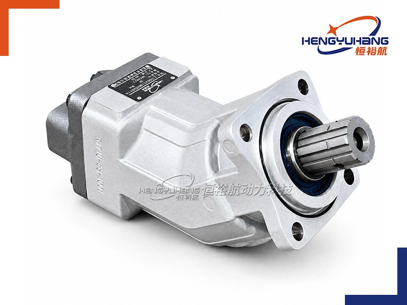
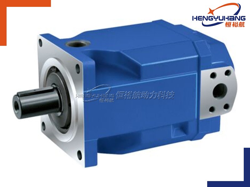
 WhatsApp
 Email
 +86 19918575358