CASAPPA Replacements
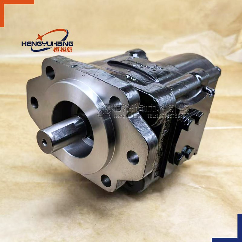
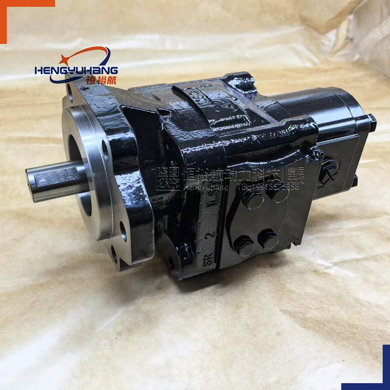
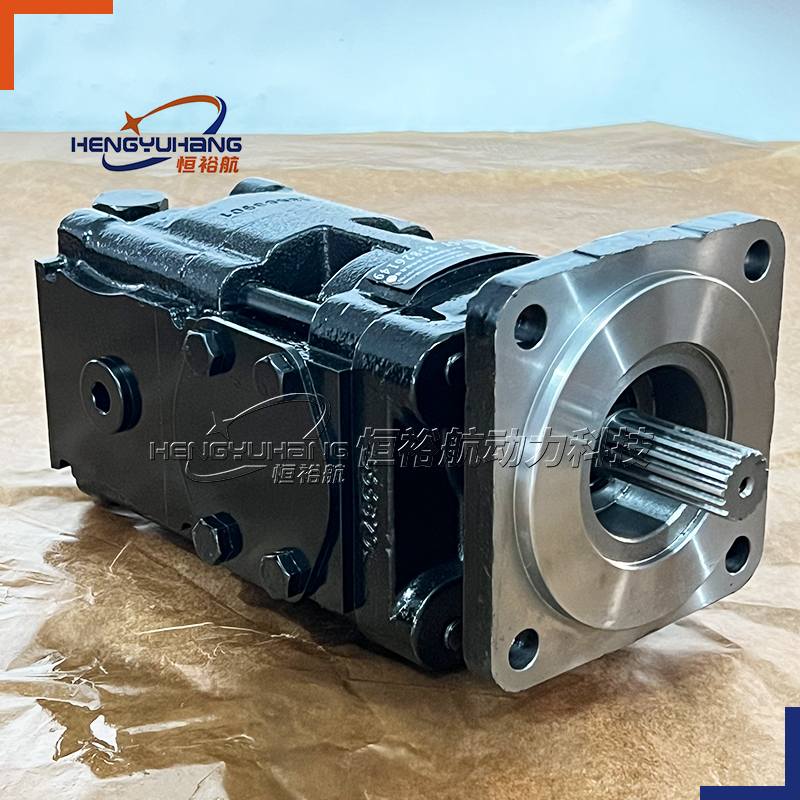
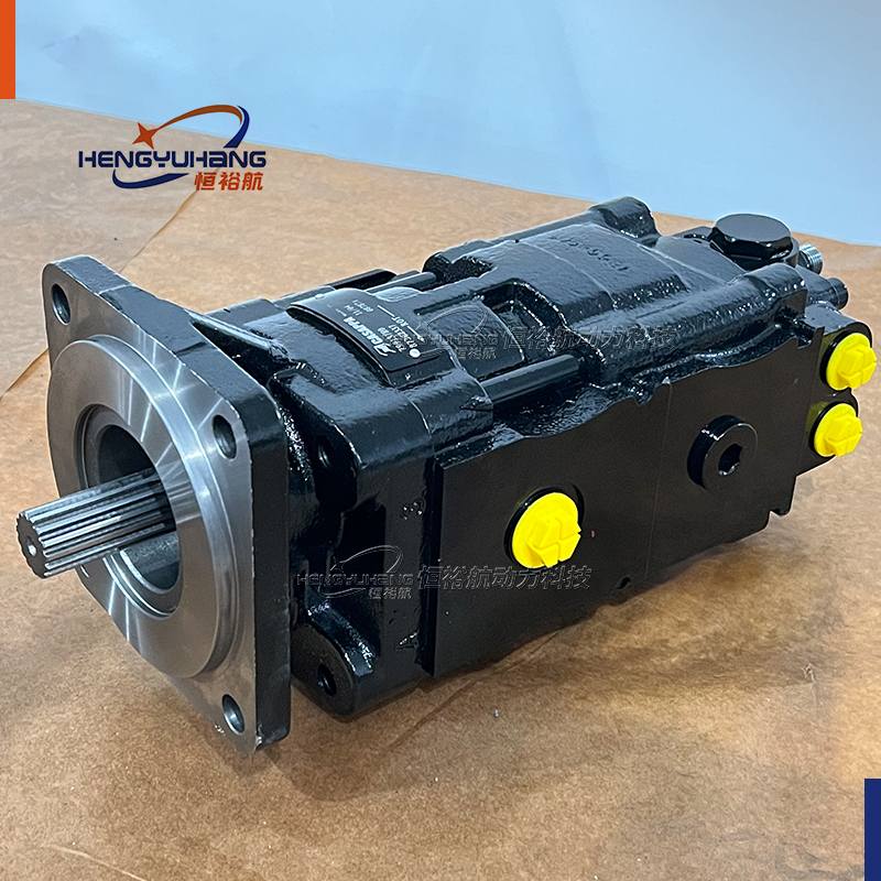
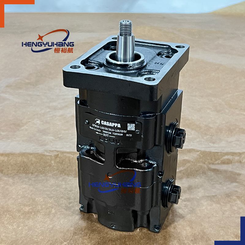
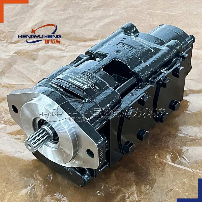
CASAPPA Hydraulic Gear pump KP30.24-33S3
CASAPPA KP30.24-33S3-LMD/MB-45-HSC/PLP20 is a KAPPA 30 cast-iron external gear double pump — a KP 30•24 group 3 gear section at the drive-shaft end with a Polaris 20 gear section built behind it on the same shaft line, so one drive take-off feeds two independent circuits. The front section displaces 24.03 cm³/rev (1.47 in³/rev), the rear Polaris 20 section 8.26 cm³/rev (0.50 in³/rev) in the PLP 20•8 reference size — 32.29 cm³/rev (1.97 in³/rev) together. Body and mounting flange are cast iron of superior mechanical specification, and each section carries a precision external gear pair on sleeve bearings between pressure-balanced thrust plates that compensate for wear and hold volumetric efficiency as pressure rises. Configured here with the SAE "BB" straight drive shaft (code 33), the SAE "B" 2–4 hole mounting flange (code S3) and side-positioned SAE flanged J518 ports — inlet MD, outlet MB — the front section runs from 350 to 3,000 r/min and is rated 280 bar (4,060 psi) relief-valve setting and 300 bar (4,350 psi) peak in the compact HSC body design, moving 72.1 l/min of oil at maximum speed; the rear section adds 24.8 l/min at its 250 bar rating, for 96.9 l/min from the assembly. Two circuits, high pressure and high flow, inside one compact cast-iron envelope, with low noise emission and the long working life the KAPPA construction is specified for.
| CASAPPA KP30.24-33S3-LMD/MB-45-HSC/PLP20 Applications
The pump is engineered to feed two continuous-duty hydraulic circuits from a single drive point on mobile and industrial machinery. It is used on building and construction equipment, material handling machinery, forestry machines and fan drives, and across the wider KAPPA application range on agricultural implements, cranes, winches, mixers, presses and machine tools — one section supplying pressurised flow for cylinders, motors and valve blocks while the second section feeds a separate circuit, such as steering, pilot, lubrication or cooling, from the same shaft. SAE and European standard mounting flanges, drive shafts and ports let the unit be fitted to existing machinery without modifying the driveline, the mounting or the pipework.
3. Key parameters
Product Model: KP30.24-33S3-LMD/MB-45-HSC/PLP20
Brand Replacement: CASAPPA OEM or as requested.
Displacement: front section 24.03 cm³/rev (1.47 in³/rev) + rear Polaris 20 section 8.26 cm³/rev (0.50 in³/rev) — 32.29 cm³/rev (1.97 in³/rev) total
Rotation Direction: clockwise (D)
Peak Pressure: 300 bar (4,350 psi) at the front section with the HSC body design — 320 bar (4,640 psi) with the GS high-performance level; 300 bar (4,350 psi) at the rear section
Min./max. speed (350 / 3,000 r/min at the front section), the relief-valve and peak pressure ratings, the drain-line limits, the flange, clamp, cover and port torques, and the torque the assembly draws from the drive shaft are listed in full in Techspecs below.
| Overview of CASAPPA KP30.24-33S3-LMD/MB-45-HSC/PLP20
CASAPPA KP30.24-33S3-LMD/MB-45-HSC/PLP20 is a KAPPA 30 multiple pump — the double-pump variant of Casappa's cast-iron external gear range, built here with a Polaris 20 gear section as the rear unit. Casappa builds the KAPPA range around a body and a mounting flange in cast iron of superior mechanical specification, and the KAPPA 30 is a solid, compact two-piece construction that allows several functions to be packed into a reduced space. Inside each section the external gear pair runs on sleeve bearings between pressure-balanced thrust plates, so the assembly stays rigid and keeps its volumetric efficiency as pressure rises and as the unit wears.
Its function in a circuit is to draw oil from the reservoir and convert drive-shaft rotation into pressurised flow — here twice over. The front section is a KP 30•24 at 24.03 cm³/rev (1.47 in³/rev), rated 280 bar (4,060 psi) relief-valve setting and 300 bar (4,350 psi) peak in the compact HSC body design and turning up to 3,000 r/min; the rear section is a Polaris 20 gear section of the PLP 20 series — shown here at the reference PLP 20•8 rating of 8.26 cm³/rev (0.50 in³/rev), rated 250 bar (3,625 psi) continuous, 280 bar (4,060 psi) system pressure and 300 bar (4,350 psi) peak. Both sections share one shaft line and are stacked on the drive-shaft end first, the section with the greater power requirement at the front and the smaller behind it. This unit carries the SAE "B" 2–4 hole mounting flange (code S3), the SAE "BB" straight drive shaft (code 33) and SAE flanged J518 side ports — inlet MD, outlet MB. The same range can be ordered with European, SAE and ISO mounting flanges, nine drive-shaft options and threaded, split-flange or flanged ports, so one pump family covers a wide spread of existing installations.
Because the sections are driven through the first shaft and through an internal connecting shaft, the pressure each section may be run at is bounded by the torque those shafts can transmit — see Techspecs.
| Dimension of CASAPPA KP30.24-33S3-LMD/MB-45-HSC/PLP20
[Drawing placeholder — insert the dimensional drawing screenshot here]
Reference dimensions published for the KP 30 / PLP 20 double pump with the SAE "B" two-hole mounting flange and SAE flanged (SSM) side ports. The letters correspond to the dimensional drawing.
| Ref. | mm | in |
|---|---|---|
| A — KP 30•24 front section | 83.3 | 3.28 |
| B — KP 30•24 front section, SAE flanged (SSM) side ports | 38 | 1.50 |
| C — PLP 20•8 rear section | 28.3 | 1.11 |
| D — PLP 20•8 rear section | 51.8 | 2.04 |
The mounting flange enters the length dimension: the KP 30•24 front section measures 83.3 mm (3.28 in) with the SAE "B" 2-hole flange (code K9), 86.5 mm (3.41 in) with the S9 flange and 116.5 mm (4.59 in) with the S6 flange.
Interface data needed with the drawing:
| Item | Value |
|---|---|
| Mounting flange | SAE "B" 2–4 holes, code S3 — conforms to SAE J744 |
| Drive shaft | SAE "BB" straight, shaft code 33 — mounting face S3 |
| Ports position | L — inlets and outlets on the side |
| Ports IN / OUT | SAE flanged J518 (SSM) — inlet MD (30.5 mm nominal), outlet MB (19 mm nominal) |
| Rear section ports | SAE flanged J518 (SSM) — PLP 20•8 rear section: inlet MA (12.5 mm nominal), outlet MA (12.5 mm nominal) |
| Version | 0 — without outboard bearing |
| Front section body design | HSC — Compact |
| Rear section | PLP 20 — Polaris 20 gear section, cast-iron rear cover (standard) |
| Mounting flange bolt tightening torque | 70 ±7 Nm (558 ÷ 682 lbf in) |
| Body clamp bolt tightening torque | 140 ±14 Nm (1,115 ÷ 1,363 lbf in) |
| Rear cover screw tightening torque | 45 ±4.5 Nm (358 ÷ 438 lbf in) with the aluminium cover · 70 ±7 Nm (558 ÷ 682 lbf in) with the cast-iron cover |
| Pump Installation Specifications CASAPPA KP30.24-33S3-LMD/MB-45-HSC/PLP20
A KAPPA 30 double pump of different groups is written as one section after another, separated by a slash: the section before the separator is the front section — the one at the drive-shaft end — and the section after it is the rear section. The string runs through 14 positions; a position left unwritten takes its standard value.
Code structure — KAPPA 30 double pumps of different groups, KP30 / PHP20 and KP30 / PLP20:
| Pos. | Meaning | Options |
|---|---|---|
| 1 | Type | front section KP 30•19,5 / •22 / •24 / •27 / •29 / •31 / •34 / •38 / •41 / •43 / •46 / •51 / •56 / •61 / •73 / •82 · rear section PLP 20•4 / •6,3 / •7,2 / •8 / •9 / •10,5 / •11,2 / •14 / •16 / •19 / •20 / •24,5 / •25 / •27,8 / •31,5 |
| 2 | Drive shaft | 83 European tapered 1:8 / 04 SAE "B" spline 13 T / 32 SAE "B" straight / 05 SAE "BB" spline 15 T / 33 SAE "BB" straight / A8 SAE "B" spline 13 T / A5 SAE "BB" spline 15 T / 06 SAE "C" spline 14 T / A6 SAE "CC" spline short type 14 T |
| 3 | Mounting flange | E3 European / S1, S2, S9 SAE "A" 2 holes / S3 SAE "B" 2–4 holes / K9 SAE "B" 2 holes / S6 SAE "C" 4 holes / S8 SAE "C" 2 holes / Q3 SAE "C" 2 holes short type |
| 4 | Ports position | L — inlets and outlets on the side |
| 5 | Ports IN/OUT | European flanged ED/EB for KP 30•22 to •61, EF/ED for •73 · SAE flanged (SSM) MC/MB for •22–•38, MD/MC for •41–•51, ME/MD for •56–•73 · SAE flanged (SSS) SC/SB for •22–•38, SD/SC for •41–•51, SE/SD for •56–•73 · SAE straight thread (ODT) OF/OD for •22–•38, OG/OF for •41–•73 · GAS straight thread (BSPP) GF/GE for •22–•38, GG/GF for •41–•73 |
| 6 | Connecting shaft | 45 — the connecting shaft of the KP30 / PHP20 and KP30 / PLP20 combinations |
| 7 | Body for common inlet | no code two separate inlets (standard) / N7 common inlet, KP30 / PHP20 and KP30 / PLP20 |
| 8 | Body design | CSC Standard / HSC Compact / BSC High performance |
| 9 | Rear cover options | no code cast iron (standard) / L aluminium |
| 10 | Rotation | S anti-clockwise / D clockwise |
| 11 | Outboard bearing options | no code (0) without outboard bearing / 1 / 3 / 6 with outboard bearing |
| 12 | Seals | no code Buna NBR (standard) / V Viton-FKM / T-PV HNBR seals with Viton-FKM shaft seals / N Bz Buna NBR with bronze thrust plates / V Bz Viton-FKM with bronze thrust plates |
| 13 | Shaft seal options | no code standard seal / D shaft seal with wiper seal / C4 high-pressure special shaft seal |
| 14 | Painting | no code without painting (standard) / VNR01 black / VGR01 grey |
Position 5 lists the port pair in IN/OUT order for pumps and in OUT/IN order for motors — which is why the same flange appears as MD/MB on a pump and as MB/MD on a motor. The rear section of a KP30 / PLP20 combination carries the ports of the Polaris 20 size fitted.
| Reading your code: KP30.24-33S3-LMD/MB-45-HSC/PLP20
| Pos. | Code | Meaning |
|---|---|---|
| 1 | KP 30•24 | Front section: KAPPA 30 group 3 pump, 24.03 cm³/rev (1.47 in³/rev) |
| 2 | 33 | Drive shaft: SAE "BB" straight — mounting face S3 |
| 3 | S3 | Mounting flange: SAE "B" 2–4 holes, conforms to SAE J744 |
| 4 | L | Ports position: inlets and outlets on the side |
| 5 | MD/MB | Ports IN/OUT: SAE flanged J518 (SSM) — inlet MD, 30.5 mm nominal with M10 bolts; outlet MB, 19 mm nominal with M10 bolts |
| 6 | 45 | Connecting shaft: the KP30 / PLP20 combination code |
| 7 | not written | Body for common inlet: two separate inlets — the standard arrangement |
| 8 | HSC | Body design: Compact |
| / | PLP 20 | Rear section: Polaris 20 gear section. Its displacement is written together with the rear-section type — PLP 20•4 through PLP 20•31,5; this order code is written without it, so the figures on this page use the reference rear-section size PLP 20•8. Every field left unwritten takes its standard value |
| Assembly rules for KAPPA 30 multiple pumps
In applications where the input power requirement of each section varies, the section with the greater requirement must be at the drive-shaft end, and progressively smaller to the rear.
Features and performance are the same as the corresponding single pumps, but pressures must be limited by the transmissible torque of the drive and connecting shafts.
The maximum rotational speed is that of the lowest-rated single unit incorporated — here 3,000 r/min, the rating of the KP 30•24 front section, against 3,500 r/min at the PLP 20•8 rear section.
The torque absorbed from the shaft of the first pump results from the sum of the torques due to all sections, and must not exceed the maximum torque limit given for the shaft of the first pump.
For multiple pumps with more than two sections a bracket is recommended.
Techspecs
Performance
| Parameter | Value |
|---|---|
| Type | KP 30•24 + PLP 20 — KAPPA 30 cast-iron external gear double pump, KP 30 front section + Polaris 20 rear section |
| Displacement, front section | 24.03 cm³/rev (1.47 in³/rev) |
| Displacement, rear section | 8.26 cm³/rev (0.50 in³/rev) — PLP 20•8, the reference rear-section size used for the figures on this page; the rear-section displacement is written together with the rear-section type, from PLP 20•4 to PLP 20•31,5 |
| Total displacement | 32.29 cm³/rev (1.97 in³/rev) |
| Relief valve setting p2, front section | 280 bar (4,060 psi) — HSC body design |
| Peak pressure p3, front section | 300 bar (4,350 psi) — HSC body design |
| High performance level (GS), front section | 300 / 320 bar (4,350 / 4,640 psi) relief valve setting / peak |
| Rear section pressure, PLP 20•8 | 250 / 280 / 300 bar (3,625 / 4,060 / 4,350 psi) continuous / system / peak |
| Max. speed | 3,000 r/min — the assembly maximum is that of the lowest-rated section incorporated; the PLP 20•8 rear section is rated 3,500 r/min |
| Min. speed | 600 r/min — the KP 30•24 front section is rated from 350 r/min and the PLP 20•8 rear section is published with a 600 r/min minimum |
| Theoretical flow at 3,000 r/min | 72.1 l/min from the front section + 24.8 l/min from the rear section = 96.9 l/min in total (displacement × speed ÷ 1,000) |
| Theoretical flow at 1,500 r/min | 36.0 l/min + 12.4 l/min = 48.4 l/min in total |
| Absorbed torque | the torque drawn from the drive shaft is the sum of the torques of all sections (M = Δp × V ÷ 62.83 ÷ ηhm, with ηhm ≈ 0.90). At the pressures above the front section draws approximately 119 Nm and the rear section approximately 36.5 Nm; the sum of approximately 156 Nm must stay within the transmissible torque of the drive shaft and of the connecting shaft |
| Max. torque of the drive shaft (code 33) | 280 Nm (2,470 lbf in) |
| Connecting shaft | 110 Nm (974 lbf in) for the standard connecting shaft of the KP30 / PLP20 combination; a special connecting shaft is available up to 170 Nm (1,505 lbf in) |
| Reversible versions | maximum pressures 15 % lower than the values above |
| Max. drain line pressure, single-rotation pump | 0.5 bar (7 psi) |
| Max. drain line pressure, reversible pump | 5 bar (73 psi) |
| Efficiency | calculated from the design formulas Q = Qtheor. × ηv, M = Mtheor. ÷ ηhm, ηt = ηv × ηhm; ηv ≈ 0.98, ηhm ≈ 0.90, ηt ≈ 0.88. Performance curves are published for each displacement |
| Pressure definitions | p2 is the relief valve setting; p3 is the peak of pressure, the maximum pressure allowed, corresponding to the overshoot of the relief valve. Both the relief valve setting and the overshoot must remain below their limits |
Interfaces and configuration
| Parameter | Value |
|---|---|
| Rotation | S anti-clockwise / D clockwise, looking at the drive shaft |
| Mounting flange | SAE "B" 2–4 holes, code S3 — conforms to SAE J744 |
| Drive shaft | SAE "BB" straight, shaft code 33 — mounting face S3 |
| Ports position | L — inlets and outlets on the side |
| Ports IN / OUT | SAE flanged J518 (SSM), 3000 PSI series, metric thread ISO 60° to ISO/R 262 — inlet MD, 30.5 mm nominal (1.20 in); outlet MB, 19 mm nominal (0.75 in) |
| Rear section ports | SAE flanged J518 (SSM) — PLP 20•8 rear section: inlet MA (12.5 mm nominal, 38.1 mm flange, M8 × 14), outlet MA (12.5 mm nominal, 38.1 mm flange, M8 × 14) |
| Version | 0 — without outboard bearing |
| Body design | HSC — Compact |
| Rear cover | cast iron (standard); aluminium available (code L) |
| Rear pump thrust plate | standard; high speed available (code AV) for rear section types 16 to 20 |
| Seals | Buna NBR (standard); Viton-FKM (code V); HNBR with Viton-FKM shaft seals (code T-PV); and the bronze thrust-plate versions (N Bz / V Bz) |
| Construction | Two-piece cast-iron construction in each section: body and mounting flange in cast iron, external gear pair on sleeve bearings, pressure-balanced thrust plates |
| Mounting flange bolt tightening torque | 70 ±7 Nm (558 ÷ 682 lbf in) |
| Body clamp bolt tightening torque | 140 ±14 Nm (1,115 ÷ 1,363 lbf in) |
| Rear cover screw tightening torque | 45 ±4.5 Nm (358 ÷ 438 lbf in) with the aluminium cover · 70 ±7 Nm (558 ÷ 682 lbf in) with the cast-iron cover |
| Port bolt tightening torque | MD — M10 thread, 17 mm deep, flange 58.7 × 30.2 mm: 20 +1 Nm (177 ÷ 186 lbf in) on the low-pressure side, 35 +2.5 Nm (310 ÷ 332 lbf in) on the high-pressure side · MB — M10 thread, 14 mm deep, flange 47.6 × 22.2 mm: 20 +1 Nm (177 ÷ 186 lbf in) on the low-pressure side, 20 +1 Nm (177 ÷ 186 lbf in) on the high-pressure side · MA (rear section) — M8 thread, 14 mm deep, flange 38.1 mm: 15 +1 Nm (133 ÷ 142 lbf in) on both sides. On this pump MD is the inlet and MB the outlet, so MD is torqued to its low-pressure value and MB to its high-pressure value. The high-pressure-side values are obtained at 350 bar; for reversible rotation only the high-pressure-side torque is used |
Operating conditions
| Parameter | Value |
|---|---|
| Fluid | Mineral-oil-based hydraulic fluid to ISO/DIN; fire-resistant fluids on request (specify the fluid type when ordering) |
| Inlet pressure range (pump) | 0.7 ÷ 3 bar abs. (10 ÷ 44 psi); above 1.5 bar abs. (22 psi) a specific shaft sealing must be used |
| Viscosity — recommended | 12 to 100 mm²/s (cSt) [60 to 456 SSU] |
| Viscosity — permitted | up to 750 mm²/s (cSt) [3,410 SSU] |
| Fluid temperature, N seals | −25 °C to 80 °C continuous (−13 °F to 176 °F); 100 °C (212 °F) max. peak |
| Fluid temperature, V / T-PV seals | −25 °C to 110 °C continuous (−13 °F to 230 °F); 125 °C (257 °F) max. peak |
| Cold start | min. inlet pressure 0.5 bar abs. (7 psi); outlet pressure ≤ 50 bar (725 psi); speed ≤ 1,500 r/min; max. oil viscosity 2,000 mm²/s (cSt) [9,100 SSU]; min. temperature −40 °C (−40 °F) |
| Recommended contamination | at Δp < 140 bar: NAS 1638 class 10 / ISO 4406 21/19/16 · at 140 < Δp < 210 bar: class 9 / 20/18/15 · at Δp > 210 bar: class 8 / 19/17/14. Achieved with a β10(c) ≥ 200 filter element to ISO 16889, 10 μm. The front section of this pump runs above 210 bar, so the third row applies |
| Storage | dry environment; max. 24 months under ideal conditions; ideal storage temperature 5 °C to 20 °C (41 °F to 68 °F) |
| Dimensions | see section 2. |
Advantages
Two pumps, one drive point
A 24.03 cm³/rev KP 30 front section plus a Polaris 20 rear section on the same shaft line give 32.29 cm³/rev and 96.9 l/min at 3,000 r/min, so a single take-off drives two circuits — for example a main working circuit plus steering, pilot or cooling — with one mounting flange and one coupling.
Cast-iron body and mounting flange
The KAPPA range is built around a body and a mounting flange in cast iron of superior mechanical specification, and the rigidity of that assembly is what holds reliability and high volumetric efficiency at high operating pressures.
High pressure from a compact body
280 bar (4,060 psi) relief-valve setting and 300 bar (4,350 psi) peak at the front section in the HSC body design, and 300 / 320 bar (4,350 / 4,640 psi) with the GS high-performance level — with the front section measuring 83.3 mm (3.28 in) on the mounting face.
Two independent pressure levels
The KP 30•24 front section runs to 280 bar while the Polaris 20 rear section is rated 250 / 280 / 300 bar — one drive point feeding a high-pressure working circuit and a moderate-pressure service circuit at the same time.
Solid, compact construction
The KAPPA 30 packs several functions into a reduced space — which is the point of a multiple pump: two circuits inside one pump envelope instead of two separate pumps.
Low noise emission
The external gear design keeps running noise low, which is a requirement on fan drives, municipal machinery and equipment working close to the operator.
Exceptional working life expectancy
Pressure-balanced thrust plates compensate for wear, so each section keeps its flow as the unit ages.
Torque-checked build
The 33 drive shaft is rated 280 Nm (2,470 lbf in) and the KP30 / PLP20 connecting shaft 110 Nm (974 lbf in), against an absorbed torque of approximately 156 Nm at the drive shaft and 36.5 Nm at the rear section on the pressures above — both well inside the limits.
SAE standard interface
The S3 flange is an SAE J744 2–4 hole flange, the code-33 drive shaft is an SAE "BB" straight shaft, and the MD/MB and MA ports are SAE J518 flanged ports taking standard split-flange fittings — bolt torques for the flange, the clamp, the cover and every port are published in Techspecs.
Wide combination choice
European, SAE and ISO mounting flanges, nine drive shafts, four port positions, threaded, split-flange or flanged ports and fifteen Polaris 20 rear sizes let the same pump family be matched to an existing driveline, mounting and pipework.
Common-inlet option available
The same construction can be ordered with a common inlet body (code N7) when both sections should draw from one suction line.
6. Reference of CASAPPA KP30.24-33S3-LMD/MB-45-HSC/PLP20
6.1 The KP 30 range — same series, all displacements
Every size below is a valid position 1 in the KP 30 ordering code, as a single pump, as a gear motor (KM 30) or as a section of a multiple pump. The ratings are published as relief-valve setting p2 and peak pressure p3 for side-port units; reversible pumps and motors are rated 15 % lower than the values shown, and the two rating columns are given where the catalogue publishes them.
| Pump type | Displacement | p2 / p3 — standard body design | p2 / p3 — GS high-performance build | Max. speed | Min. speed |
|---|---|---|---|---|---|
| KP 30•19,5 | 19.63 cm³/rev (1.20 in³/rev) | 290 / 310 bar | 300 / 320 bar | 3,000 r/min | 350 r/min |
| KP 30•22 | 21.99 cm³/rev (1.34 in³/rev) | 290 / 310 bar | 300 / 320 bar | 3,000 r/min | 350 r/min |
| KP 30•24 | 24.03 cm³/rev (1.47 in³/rev) | 280 / 300 bar | 300 / 320 bar | 3,000 r/min | 350 r/min |
| KP 30•27 | 26.7 cm³/rev (1.63 in³/rev) | 270 / 290 bar | 300 / 320 bar | 3,000 r/min | 350 r/min |
| KP 30•29 | 29.06 cm³/rev (1.77 in³/rev) | 270 / 290 bar | 300 / 320 bar | 3,000 r/min | 350 r/min |
| KP 30•31 | 30.63 cm³/rev (1.87 in³/rev) | 250 / 270 bar | 300 / 320 bar | 3,000 r/min | 350 r/min |
| KP 30•34 | 34.56 cm³/rev (2.11 in³/rev) | 240 / 260 bar | 300 / 320 bar | 3,000 r/min | 350 r/min |
| KP 30•38 | 39.27 cm³/rev (2.40 in³/rev) | 240 / 260 bar | 300 / 320 bar | 3,000 r/min | 350 r/min |
| KP 30•41 | 41.62 cm³/rev (2.54 in³/rev) | 250 / 270 bar | — | 3,000 r/min | 350 r/min |
| KP 30•43 | 43.98 cm³/rev (2.68 in³/rev) | 250 / 270 bar | — | 3,000 r/min | 350 r/min |
| KP 30•46 | 46.34 cm³/rev (2.83 in³/rev) | 240 / 260 bar | — | 3,000 r/min | 350 r/min |
| KP 30•51 | 51.83 cm³/rev (3.16 in³/rev) | 240 / 260 bar | — | 2,500 r/min | 350 r/min |
| KP 30•56 | 56.54 cm³/rev (3.45 in³/rev) | 220 / 240 bar | — | 2,500 r/min | 350 r/min |
| KP 30•61 | 61.26 cm³/rev (3.74 in³/rev) | 260 / 280 bar | — | 2,500 r/min | 350 r/min |
| KP 30•73 | 73.82 cm³/rev (4.50 in³/rev) | 250 / 270 bar | — | 2,500 r/min | 350 r/min |
| KP 30•82 | 81.68 cm³/rev (4.98 in³/rev) | — | 230 / 250 bar | 2,800 r/min | 350 r/min |
For KP 30•61 and •73 the catalogue publishes the 260 / 280 and 250 / 270 bar values with the Compact body design; the sizes up to KP 30•38 are published with both the standard and the GS high-performance builds. Any two KP 30 sizes can be combined into a same-group double pump with the larger section at the drive-shaft end, or a KP 30 section can be combined with a Polaris 20 or Polaris HP 20 section as a different-group double pump. The matching gear-motor range is KM 30, with the same displacements.
6.2 The Polaris 20 range — the rear section of this assembly
The rear section of a KP30 / PLP20 double pump is a Polaris 20 gear unit. Displacements, pressures and speeds of the PLP 20 series are listed below; the pressures are given as continuous p1, system pressure p2 and peak p3.
| Rear pump type | Displacement | p1 | p2 | p3 | Max. speed | Min. speed |
|---|---|---|---|---|---|---|
| PLP 20•4 | 4.95 cm³/rev (0.30 in³/rev) | 250 bar | 280 bar | 300 bar | 4,000 r/min | 600 r/min |
| PLP 20•6,3 | 6.61 cm³/rev (0.40 in³/rev) | 250 bar | 280 bar | 300 bar | 4,000 r/min | 600 r/min |
| PLP 20•7,2 | 7.29 cm³/rev (0.44 in³/rev) | 250 bar | 280 bar | 300 bar | 4,000 r/min | 600 r/min |
| PLP 20•8 | 8.26 cm³/rev (0.50 in³/rev) | 250 bar | 280 bar | 300 bar | 3,500 r/min | 600 r/min |
| PLP 20•9 | 9.17 cm³/rev (0.56 in³/rev) | 250 bar | 280 bar | 300 bar | 3,500 r/min | 600 r/min |
| PLP 20•10,5 | 10.9 cm³/rev (0.66 in³/rev) | 250 bar | 280 bar | 300 bar | 3,500 r/min | 600 r/min |
| PLP 20•11,2 | 11.23 cm³/rev (0.69 in³/rev) | 250 bar | 280 bar | 300 bar | 3,500 r/min | 600 r/min |
| PLP 20•14 | 14.53 cm³/rev (0.89 in³/rev) | 250 bar | 280 bar | 300 bar | 3,500 r/min | 500 r/min |
| PLP 20•16 | 16.85 cm³/rev (1.03 in³/rev) | 250 bar | 280 bar | 300 bar | 3,000 r/min | 500 r/min |
| PLP 20•19 | 19.09 cm³/rev (1.16 in³/rev) | 200 bar | 220 bar | 240 bar | 3,000 r/min | 500 r/min |
| PLP 20•20 | 21.14 cm³/rev (1.29 in³/rev) | 200 bar | 220 bar | 240 bar | 3,000 r/min | 500 r/min |
| PLP 20•24,5 | 24.84 cm³/rev (1.52 in³/rev) | 170 bar | 190 bar | 210 bar | 2,500 r/min | 500 r/min |
| PLP 20•25 | 26.42 cm³/rev (1.61 in³/rev) | 170 bar | 190 bar | 210 bar | 2,500 r/min | 500 r/min |
| PLP 20•27,8 | 28.21 cm³/rev (1.72 in³/rev) | 130 bar | 150 bar | 170 bar | 2,000 r/min | 500 r/min |
| PLP 20•31,5 | 33.03 cm³/rev (2.01 in³/rev) | 130 bar | 150 bar | 170 bar | 2,000 r/min | 500 r/min |
The rear-section ports follow the size: PLP 20•4 to •11,2 carry MA/MA and PLP 20•14 to •20 carry MB/MA, and the rear-section port pair is written with the rear-section type.
6.3 Complete order numbers identified on the market
Complete KAPPA 30 double-pump order numbers of the KP 30 range. Reference only — each number is valid only in the exact configuration it describes.
| Order number |
| KP30.24-33S3-LMD/MB-45-HSC/PLP20 |
| KP30.34-A8K9-LMD/MB-KSL/GS/30.24 |
| KP30.34-A8K9-LMD/MB-HSC/PLP20.16 |
| KP30.19,5-A8K9-LMC/MB-45-HSC/GS/PLP20.16 |
| KP30.27-A8K9-LGF/GE-45-HSC/PLP20.16 |
| KP30.29-A8K9-LOF/OD-45-HSC/PLP |
| KP30.43-A8K9-LMD/MB-45/PLP |
| KP30.51-A5K9-2ME/MC-45-BSC/PLP |
| KP30.51-A8K9-LME/MC-KSL/GS/30.27 |
| KP30.51D0-06S8-LMD/MC-N-CSC |
| KP30.38-05S6-LMF-00-M5-KSL-30 |
Official Casappa order examples for KAPPA 30 double pumps of different groups, for reference:
| Order number |
| KP 30•19,5-A8 K9-L MC/MB-45-HSC/GS/PLP 20•16-L /MA-N7 S-T-PV/FS-L-AV (ANF3) (CN) (VNR01) |
| KP 30•19,5-05 S6-L GF/GE-45-HSC/GS/PLP 20•16-L /GD-N7-L101 S-T-PV/FS-L-AV (ANF3) (CN) (VNR01) |
| KP 30•51 - A8 K9 - L MD/C - 45 - CSC / PLP 20•14 - L MB/MA - - L - S 1 / FS V - C4 VNR01 |
7. Brand Replacement
HENGYUHANG supplies a replacement for the CASAPPA KAPPA 30 gear pump series, including KP30.24-33S3-LMD/MB-45-HSC/PLP20 and the rest of the KP 30 size range, in single-pump and multiple-pump form. The replacement is built to the same group 3 dimensional envelope and the same international standard interfaces — European, SAE and ISO mounting flanges, the same drive-shaft families, and threaded, split-flange or flanged ports — so a machine originally fitted with a Casappa KAPPA 30 pump can be returned to service without modifying the driveline, the mounting or the pipework.
Because a multiple pump is built section by section, the section order, the drive and connecting shafts and the torque limits decide what a replacement may be run at. Replacement units are supplied to Casappa's published interface and dimension data for the KAPPA 30 group, and fitment is decided by the ordering code of the original pump — please quote the complete original order number when enquiring.
8. Applications of CASAPPA KP30.24-33S3-LMD/MB-45-HSC/PLP20
Typical applications of the KAPPA 30 gear pump family, in single and multiple-pump form:
Building and construction — supply pump on compact machines, excavators and loaders, roller and drum drives, auxiliary circuits
Material handling — lifting, tilting and positioning circuits on handling equipment, cranes and aerial platforms
Forestry — feed, conveyor, saw and attachment drives on forestry machinery
Fan drive — engine cooling fan drives and hydraulic fan circuits
Agriculture — supply and implement circuits on tractors, balers, harvesters, sprayers and seeders
Industrial hydraulics — presses, mixers, machine tools and plastic injection moulding machines
Special vehicles — municipal vehicles, cleaning vehicles and truck-mounted equipment
In these machines a multiple pump feeds two loads at once — typically a working circuit that runs continuously at moderate circuit pressure plus a second service such as steering, pilot, lubrication or cooling. The cast-iron body, the sleeve-bearing gear pairs and the pressure-balanced thrust plates are what let the assembly keep its volumetric efficiency as circuit pressure and oil temperature rise.
9. Package & Shipping
| Item | Specification |
|---|---|
| Packaging | Single unit, wooden box / export-grade packing |
| Selling unit | Single item — MOQ 1 unit |
| Net weight | Per order, according to the sections, shaft, flange and ports selected |
| Gross weight and package size | Per order, according to the shaft, flange and ports selected |
| Lead time | Per order, according to configuration and quantity |
| Shipping | Air, sea or express, quoted to destination |
| Customization | Customized packaging, nameplate and logo available for volume orders |
| Warranty | 1 year |
10. Why Choose Hengyuhang?
A hydraulic specialist, not a general trader. Quanzhou Hengyuhang Power Technology Co., Ltd. is based in Fujian, China and manufactures hydraulic gear pumps and motors, synchronous motors, multiple pump units, pumps with built-in valves and custom valve blocks.
One-piece minimum order. MOQ is one unit, so a single machine can be put back into service without committing to a production batch.
Model-level checking before you order. Send the complete original order number — for this page, the full KP30.24-33S3-…/PLP20 string — and every section, the drive and connecting shafts, the flange and the ports are run against the KAPPA 30 data before the unit is built.
Double-pump capability across two series. As a builder of multiple pump units we combine a KP 30 front section with a Polaris 20 rear section, check the torque the drive and connecting shafts will see against the 280 Nm and 110 Nm limits, and match the section order required by the application.
Coverage of the intermediate displacements. The KP 30•24 front section of this assembly is one of the KAPPA 30 intermediate sizes, and the same plant covers the range from KP 30•19,5 up to KP 30•82.
In-house production and testing. CNC machining centres, automatic gear heat-treatment lines, single-piece-flow assembly and an automatic hydraulic test bench, with ERP/MES traceability through production.
Replacement coverage across the range. The same plant supplies replacement units for a wide list of hydraulic brands and models, which keeps a mixed machine fleet on one supplier.
Customization support. OEM, ODM and OBM are offered, and customized packaging, graphics, nameplate and logo are available for distributor orders.
One-year warranty. Every unit is covered by a one-year warranty.
Responsive after-sales. Online support for installation and application questions.
CASAPPA KP30.24-33S3-LMD/MB-45-HSC/PLP20 Cast Iron External Gear Pump is a fixed-displacement external gear pump from the CASAPPA KP30 series, supplied as an OEM configuration. It features a solid cast iron body and delivers 24 cm³/rev displacement, with a built-in valve and stable output. Designed for reliable, low-noise operation, it provides long service life and high volumetric efficiency across demanding mobile and industrial applications.
| Applications
The KP30.24-33S3-LMD/MB-45-HSC/PLP20 gear pump is widely used in mobile machinery (tractors, agricultural implements, sprayers, small loaders), industrial machinery (machine tools, presses, conveyor systems) and special vehicles, delivering efficient and dependable hydraulic power in OEM-built equipment.
| Technical Specifications
| Parameter | Specification |
|---|---|
| Brand | CASAPPA |
| Model | KP30.24-33S3-LMD/MB-45-HSC/PLP20 |
| Series | KP30 (Group 3) — OEM configuration |
| Product Type | Cast iron external gear pump (single pump, with built-in valve) |
| Body Material | Cast iron |
| Displacement | 24 cm³/rev (1.47 in³/rev) |
| Max. Continuous Pressure | Up to 300 bar (relief valve setting, series) |
| Peak Pressure | 320 bar (series max.) |
| Max. Speed | 3000 min⁻¹ (series) |
| Flow @ 1500 rpm | 36 L/min (theoretical) |
| Volumetric Efficiency | 92 ~ 96% (typical, series) |
| Overall Efficiency | 85 ~ 90% (typical, series) |
| Mounting | Flange mount — code 33S3 (per model code) |
| Valve | Built-in valve, HSC / 45 configuration (OEM) |
| Fluid | Mineral hydraulic oil |
| Typical Applications | OEM mobile machinery, industrial machinery, special vehicles |
| Order number |
| KP30.24-33S3-LMD/MB-45-HSC/PLP20 |
| KP30.34-A8K9-LMD/MB-KSL/GS/30.24 |
| KP30.34-A8K9-LMD/MB-HSC/PLP20.16 |
| KP30.19,5-A8K9-LMC/MB-45-HSC/GS/PLP20.16 |
| KP30.27-A8K9-LGF/GE-45-HSC/PLP20.16 |
| KP30.29-A8K9-LOF/OD-45-HSC/PLP |
| KP30.43-A8K9-LMD/MB-45/PLP |
| KP30.51-A5K9-2ME/MC-45-BSC/PLP |
| KP30.51-A8K9-LME/MC-KSL/GS/30.27 |
| KP30.51D0-06S8-LMD/MC-N-CSC |
| KP30.38-05S6-LMF-00-M5-KSL-30 |
Official Casappa order examples for KAPPA 30 double pumps of different groups, for reference:
| Order number |
| KP 30•19,5-A8 K9-L MC/MB-45-HSC/GS/PLP 20•16-L /MA-N7 S-T-PV/FS-L-AV (ANF3) (CN) (VNR01) |
| KP 30•19,5-05 S6-L GF/GE-45-HSC/GS/PLP 20•16-L /GD-N7-L101 S-T-PV/FS-L-AV (ANF3) (CN) (VNR01) |
| KP 30•51 - A8 K9 - L MD/C - 45 - CSC / PLP 20•14 - L MB/MA - - L - S 1 / FS V - C4 VNR01 |
 WhatsApp
 Email
Email
 +86 19918575358