CASAPPA Replacements
CASAPPA Hydraulic Gear Pump PLP20.25
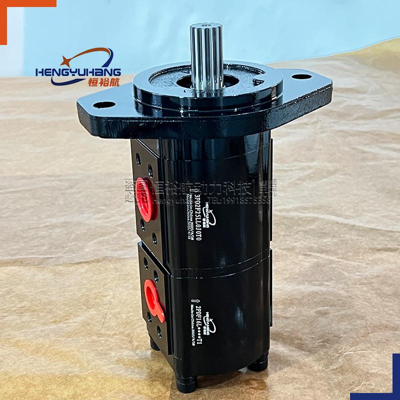
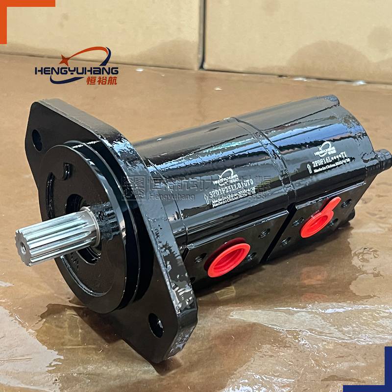
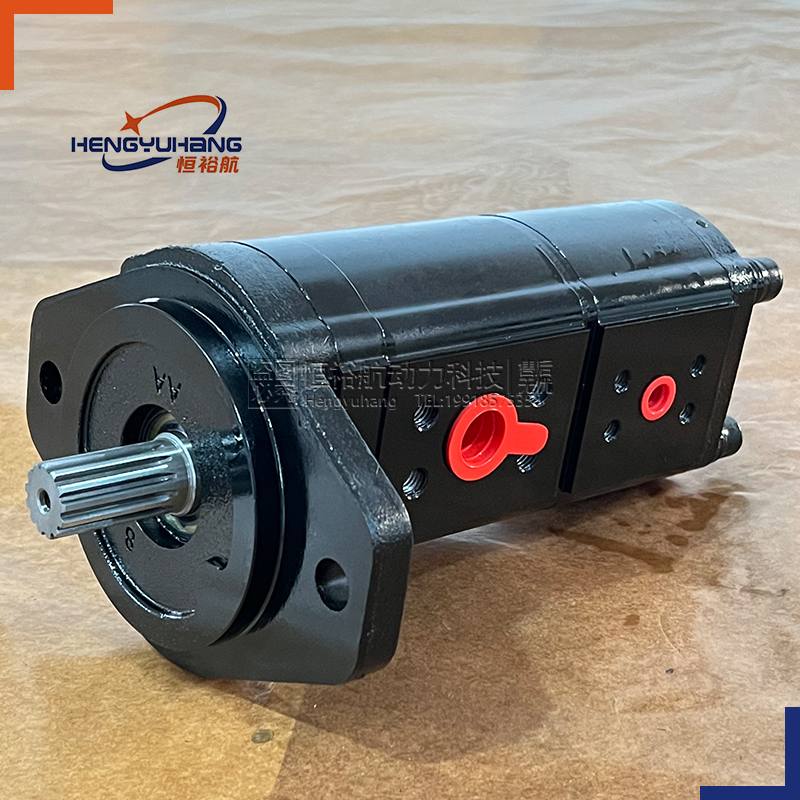
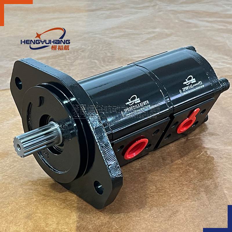
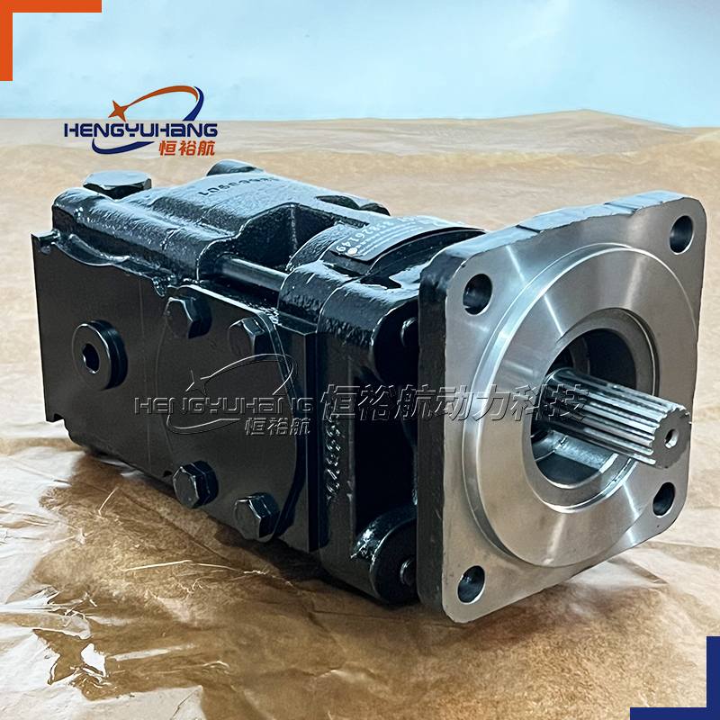
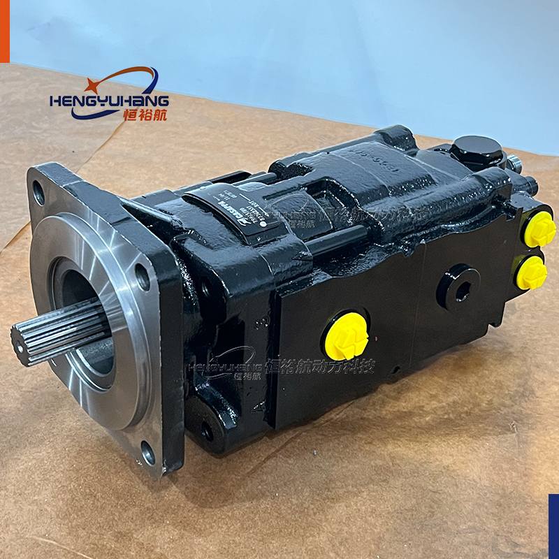
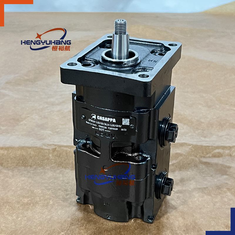
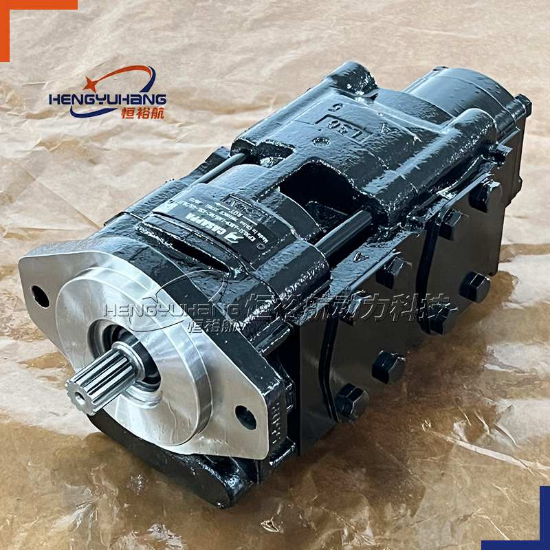
CASAPPA PLP20.25-04S5-LMC/MB/20.16-LMB/MAS/FS-LA is a two-section POLARIS 20 external gear pump — a tandem unit that puts two independent gear sections on one shaft line, driven from a single mounting flange and a single coupling. Both sections are built on Casappa's three-piece architecture: a body extruded in high-resistance aluminium alloy, a precision external gear pair carried on sleeve bearings between pressure-balanced thrust plates, and a separate mounting flange and rear cover of high mechanical strength. The front section is a PLP 20•25 at 26.42 cm³/rev (1.61 in³/rev), rated 170 bar (2,465 psi) constant operating pressure and 210 bar (3,045 psi) peak; the rear section is a PLP 20•16 at 16.85 cm³/rev (1.03 in³/rev), rated 250 bar (3,625 psi) constant and 300 bar (4,350 psi) peak. Together they displace 43.27 cm³/rev (2.64 in³/rev) and move 108.2 l/min of oil at 2,500 r/min — one drive point feeding two circuits at two different pressure levels, inside a single pump envelope. Configured here with the SAE "B" spline drive shaft (code 04), the SAE "B" two-bolt cast-iron mounting flange (code S5) and side-positioned flanged ports — front section inlet MC and outlet MB, rear section inlet MB and outlet MA, all on SAE J518 flanges of the 3000 psi standard pressure series — it is an anti-clockwise-rotation unit (S), in the version without outboard bearing, with Buna NBR seals (N), a cast-iron mounting flange with an aluminium rear cover (L) and the female spline shaft arrangement (FS).
| CASAPPA PLP20.25-04S5-LMC/MB/20.16-LMB/MAS/FS-LA Applications
The unit is engineered to feed two hydraulic circuits from one power take-off on mobile and industrial machinery. It is used on building and construction equipment, material handling machinery, agricultural and forestry machines, turf care and mower decks, and fan-drive systems, where a single engine take-off has to supply two unrelated functions at the same time — for example a high-pressure working circuit on one section and steering, pilot, cooling or auxiliary circuit on the other. Each section draws oil from the reservoir and converts drive-shaft rotation into pressurised flow for cylinders, motors and valve blocks, and holds that flow under sustained load, high duty cycles and demanding ambient conditions. The SAE "B" two-bolt flange and the SAE "B" spline shaft match the mounting and coupling that group-2 machinery is built for, the SAE J518 side ports take standard split-flange fittings, and because each section carries its own inlet and outlet, the two circuits stay hydraulically independent and can be piped separately without modifying the driveline or the mounting.
3. Key parameters
Product Model: PLP20.25-04S5-LMC/MB/20.16-LMB/MAS/FS-LA
Brand Replacement: CASAPPA OEM or as requested.
Displacement: 26.42 cm³/rev (1.61 in³/rev) front section + 16.85 cm³/rev (1.03 in³/rev) rear section = 43.27 cm³/rev (2.64 in³/rev) total
Rotation Direction: clockwise (D)
Peak Pressure: 210 bar (3,045 psi) front section · 300 bar (4,350 psi) rear section
Max. Speed: 2,500 r/min — limited by the lowest-rated section of the assembly
Min./max. speed, the per-section pressure ratings, the interface data, the port dimensions and the port torques are listed in full in Techspecs below.
| Overview of CASAPPA PLP20.25-04S5-LMC/MB/20.16-LMB/MAS/FS-LA
CASAPPA PLP20.25-04S5-LMC/MB/20.16-LMB/MAS/FS-LA is a POLARIS 20 multiple pump — the tandem version of the range. Casappa builds POLARIS pumps and motors in three pieces: a body extruded in high-resistance aluminium alloy, an external gear pair running on sleeve bearings with pressure-balanced thrust plates, and a separate mounting flange and rear cover that can be supplied in aluminium or cast iron. That layout gives a high power-to-weight ratio and keeps the wear surfaces controllable independently of the housing. In a multiple pump the sections are stacked on one shaft line, the section with the greater power requirement at the drive-shaft end, and the assembly is held together by one mounting flange at the front and a rear cover at the end.
Its function in a circuit is to draw oil from the reservoir and convert drive-shaft rotation into pressurised flow — here twice over, and at two different pressure levels. The front section is the PLP 20•25 gear set, 26.42 cm³/rev, rated 170 bar constant operating pressure, 190 bar system pressure and 210 bar peak, turning up to 2,500 r/min. The rear section is the PLP 20•16 gear set, 16.85 cm³/rev, rated 250 bar constant, 280 bar system pressure and 300 bar peak, and rated to 3,000 r/min as a single unit. Because the two sections sit on the same shaft, the assembly runs at one speed — and it is the lowest-rated of the two that sets it, so this tandem turns between 500 and 2,500 r/min.
The interfaces are written section by section. The drive end carries the SAE "B" spline shaft, code 04 — 13 teeth, 16/32 pitch, 30°, an external involute spline to SAE J498B with major diameter modified, flat root – side fit – class 1 — and it is mounted on the SAE "B" two-bolt cast-iron flange, code S5, which is the standard drive-shaft face for that shaft. Both sections take their ports on the side (position L): the front section inlet is MC, a 25.4 mm (1.00 in) port, and its outlet is MB, a 19 mm (0.75 in) port; the rear section inlet is MB, again 19 mm (0.75 in), and its outlet is MA, a 12.5 mm (0.49 in) port. All four ports are SAE flanged J518 ports of the 3000 psi standard pressure series with metric ISO 60° threads to ISO/R 262, so they take standard split-flange fittings.
The rotation is written once for the whole assembly: it is S, anti-clockwise looking at the drive shaft, and the version is the standard one, without outboard bearing. The seals are N, Buna NBR. Position 10 is L — a cast-iron mounting flange with an aluminium rear cover, which keeps a rigid cast-iron face against the driveline while saving weight on the cover at the far end of the assembly — and the code closes with FS, the female spline shaft arrangement.
Two pressures on one drive point is the reason to specify a tandem rather than two pumps: a PLP 20•16 section rated 250 bar continuous and 300 bar peak can hold a high-pressure service circuit while the PLP 20•25 section delivers 66.1 l/min at 2,500 r/min into a lower-pressure, higher-flow working circuit. The limit that governs the combination is torque, not pressure: the torque drawn from the drive shaft of the first pump is the sum of the torques of both sections, and on the standard PLP 20/20 tandem that sum must stay within 110 Nm (974 lbf in).
| Dimension of CASAPPA PLP20.25-04S5-LMC/MB/20.16-LMB/MAS/FS-LA
[Drawing placeholder — insert the dimensional drawing screenshot here]
Reference dimensions published for the PLP 20/20 tandem with side-positioned ports. The letters correspond to the dimensional drawing.
| Ref. | mm | in |
|---|---|---|
| A — front section, PLP 20•25 | 42 | 1.65 |
| A — rear section, PLP 20•16 | 34.75 | 1.37 |
| X — mounting flange thickness, version 0, flange S5 | 20 | 0.79 |
The same drawing carries the torque limit of the assembly: 110 Nm (974 lbf in) for the standard-version PLP 20/20 tandem.
Interface data needed with the drawing:
| Item | Value |
|---|---|
| Mounting flange | SAE "B", 2 bolts — flange code S5, material cast iron; X dimension for version 0 — 20 mm (0.79 in) |
| Drive shaft | SAE "B" spline, code 04 — 13 teeth, 16/32 pitch, 30°, external involute spline to SAE J498B with major diameter modified, flat root – side fit – class 1; mounting face S5 |
| Version | without outboard bearing (standard) |
| Rotation | S — anti-clockwise, looking at the drive shaft |
| Ports position | L — inlets and outlets on the side, both sections |
| Front section ports IN / OUT | SAE flanged J518 (SSM), 3000 psi series, metric thread ISO 60° to ISO/R 262 — inlet MC, port Ø 25.4 mm (1.00 in), flange Ø 52.4 mm (2.06 in), M10 bolts · outlet MB, port Ø 19 mm (0.75 in), flange Ø 47.6 mm (1.87 in), M10 bolts |
| Rear section ports IN / OUT | SAE flanged J518 (SSM) — inlet MB, port Ø 19 mm (0.75 in), flange Ø 47.6 mm (1.87 in), M10 bolts · outlet MA, port Ø 12.5 mm (0.49 in), flange Ø 38.1 mm (1.50 in), M8 bolts |
| Seals | N — Buna NBR (standard) |
| Cover options | L — cast iron mounting flange, aluminium rear cover |
| Shaft seal | standard shaft seal (position 11 not written) |
| Shaft arrangement | FS — female spline |
| Max. transmissible torque, assembly | 110 Nm (974 lbf in) |
| Pump Installation Specifications CASAPPA PLP20.25-04S5-LMC/MB/20.16-LMB/MAS/FS-LA
A POLARIS 20 multiple pump is written as one section after another, separated by a slash: the section before the separator is the front section — the one at the drive-shaft end — and the section after it is the rear section. Reading the number is the fastest way to check that the assembly will fit an existing installation, because the front section fixes the drive interface and the rear section adds its own ports, its own displacement and an independent circuit.
Code structure — POLARIS 20 multiple pumps:
| Pos. | Meaning | Options in the POLARIS 20 range |
|---|---|---|
| 1 | Type | front section PLP 20•4 / •6,3 / •7,2 / •8 / •9 / •10,5 / •11,2 / •14 / •16 / •19 / •20 / •24,5 / •25 / •27,8 / •31,5 · rear section same list |
| 2 | Drive shaft | 82 European tapered 1:8 · 54, 55 German tapered 1:5 · 46, 49, 50 straight · 03 SAE "A" spline 9 T · 01 SAE spline 10 T · 07 SAE "A" spline 11 T · 31 SAE "A" straight · 04 SAE "B" spline · 32 SAE "B" straight · 12 DIN 5482 spline · 48 straight (version 6) · B1 straight (versions 5 and 8) · 95 tang |
| 3 | Mounting flange | E2 European · B2 German · B4, B5 German 2 bolts · B6 German 4 bolts · U2 German 2 bolts · S1, S2, S9 SAE "A" 2 bolts · S5 SAE "B" 2 bolts · W8 German |
| 4 | Ports position | L inlet and outlet on the side |
| 5 | Ports IN/OUT | German flanged BE/BC · European flanged EA/EA for 4–11,2 and EB/EA for 14–31,5 · SAE flanged 3000 psi (SSM) MA/MA for 4–11,2, MB/MA for 14–16–19–20, MC/MB for 24,5–25–27,8–31,5 · SAE flanged SSS SA/SA for 4–11,2, SB/SA for 14–20, SC/SB for 24,5–31,5 · GAS straight thread GD/GD for 4–11,2 and GE/GD for 14–31,5 · SAE straight thread OC/OC for 4–11,2 and OD/OC for 14–31,5 |
| 6 | Combination type | S6 standard · S7 common inlet · Z6 separate stages |
| 7 | Rotation | S left / D right |
| 8 | Version — outboard bearing | no code without outboard bearing (standard) / W8, 5, 7, 8, 9 with outboard bearing |
| 9 | Seals | N Buna NBR (standard) / V Viton-FKM / T-PV HNBR seals with Viton-FKM shaft seals |
| 10 | Cover options | no code cast iron mounting flange and rear cover (standard) / E aluminium mounting flange and cast iron rear cover / L cast iron mounting flange and aluminium rear cover / EL aluminium mounting flange and rear cover |
| 11 | Shaft seal options | no code standard seal / D standard seal with wiper seal / C1 high back-pressure seal |
| 12 | Shaft arrangement | FS female spline |
Position 5 is listed IN/OUT on a pump and OUT/IN on a motor, which is why the same two flanges appear in the opposite order on the motor side of the range. The flange codes are read by their first letter — a port code beginning with B is a German four-bolt flange, E is a European four-bolt flange, M is an SAE flange to the 3000 psi standard pressure series, S is an SAE flange to the SSS series, G is a GAS straight thread and O is a SAE straight thread.
| Reading your code: PLP20.25-04S5-LMC/MB/20.16-LMB/MAS/FS-LA
| Segment as written | Meaning |
|---|---|
| PLP 20•25 | Front section type: POLARIS 20 pump, 26.42 cm³/rev (1.61 in³/rev) |
| 04 | Drive shaft: SAE "B" involute spline, 13 teeth, 16/32 pitch, 30°, flat root – side fit – class 1, to SAE J498B with major diameter modified; mounting face S5 |
| S5 | Mounting flange: SAE "B", 2 bolts, cast iron |
| L | Ports position: inlet and outlet on the side — both sections |
| MC/MB | Front section ports IN/OUT: SAE flanged J518 (SSM), 3000 psi series, metric thread ISO 60° to ISO/R 262 — inlet MC, port Ø 25.4 mm (1.00 in); outlet MB, port Ø 19 mm (0.75 in) |
| 20.16 | Rear section type: POLARIS 20 pump, 16.85 cm³/rev (1.03 in³/rev) |
| L | Ports position, rear section: inlet and outlet on the side |
| MB/MA | Rear section ports IN/OUT: SAE flanged J518 (SSM) — inlet MB, port Ø 19 mm (0.75 in); outlet MA, port Ø 12.5 mm (0.49 in) |
| S | Rotation: left — anti-clockwise, looking at the drive shaft |
| FS | Shaft arrangement: female spline |
| LA | Cover options: cast iron mounting flange, aluminium rear cover |
| Assembly rules for POLARIS multiple pumps
In applications where the input power requirement of each section varies, the section with the greater requirement must be at the drive-shaft end, and progressively smaller to the rear — as in this number, where the 26.42 cm³/rev front section carries the larger flow and the 16.85 cm³/rev section sits behind it.
Features and performance are the same as the corresponding single pumps, but pressures must be limited by the transmissible torque of the drive and connecting shafts.
The maximum rotational speed is that of the lowest-rated single unit incorporated — here 2,500 r/min, the rating of the PLP 20•25 front section, against 3,000 r/min for the PLP 20•16 rear section.
The torque absorbed from the shaft of the first pump results from the sum of the torques due to all sections, and must not exceed the maximum torque limit given for the shaft of the first pump — 110 Nm (974 lbf in) for the standard PLP 20/20 tandem.
The range is available in the standard version, with a common inlet and with separated stages; the standard version gives each section its own inlet and outlet, so the circuits stay independent.
Techspecs
Performance
| Parameter | Value |
|---|---|
| Type | PLP 20•25 + PLP 20•16 — POLARIS 20 external gear pump, two sections on one shaft line |
| Displacement, front section | 26.42 cm³/rev (1.61 in³/rev) |
| Displacement, rear section | 16.85 cm³/rev (1.03 in³/rev) |
| Total displacement | 43.27 cm³/rev (2.64 in³/rev) |
| Constant operating pressure p1, front section | 170 bar (2,465 psi) |
| System pressure p2, front section | 190 bar (2,755 psi) |
| Peak pressure p3, front section | 210 bar (3,045 psi) |
| Constant operating pressure p1, rear section | 250 bar (3,625 psi) |
| System pressure p2, rear section | 280 bar (4,060 psi) |
| Peak pressure p3, rear section | 300 bar (4,350 psi) |
| Max. speed | 2,500 r/min — the assembly maximum is that of the lowest-rated section incorporated; the PLP 20•16 rear section is rated 3,000 r/min |
| Min. speed | 500 r/min — both sections |
| Theoretical flow at 2,500 r/min | 66.1 l/min from the front section + 42.1 l/min from the rear section = 108.2 l/min in total (displacement × speed ÷ 1,000) |
| Theoretical flow at 1,500 r/min | 39.6 l/min + 25.3 l/min = 64.9 l/min in total |
| Absorbed torque per bar | M = Δp × V ÷ 62.83 ÷ ηhm, with ηhm ≈ 0.90 — front section 0.467 Nm per bar, rear section 0.298 Nm per bar |
| Torque at the front section's rated pressure | approximately 79.4 Nm at 170 bar |
| Torque at the rear section's rated pressure | approximately 74.5 Nm at 250 bar |
| Max. transmissible torque, assembly | 110 Nm (974 lbf in) for the standard PLP 20/20 tandem |
| Torque budget | the torque drawn from the drive shaft is the sum of the torques of both sections and must not exceed 110 Nm. At the two sections' full ratings the sum would be approximately 153.9 Nm, above the limit, so the two circuits must be apportioned — for example 170 bar on the front section + 92 bar on the rear section (106.8 Nm), or 100 bar on the front section + 200 bar on the rear section (106.3 Nm) |
| Efficiency | calculated from the design formulas Q = Qtheor. × ηv, M = Mtheor. ÷ ηhm, ηt = ηv × ηhm; ηv ≈ 0.98, ηhm ≈ 0.90, ηt ≈ 0.88. Performance curves are published for each displacement |
| Pressure definitions | p1 is the constant operating pressure, p2 the system pressure (relief valve setting) and p3 the peak of pressure — the maximum pressure allowed, corresponding to the overshoot of the relief valve. Both the relief valve setting and the overshoot must remain below their limits |
Interfaces and configuration
| Parameter | Value |
|---|---|
| Rotation | S — anti-clockwise, looking at the drive shaft. D, clockwise, is available in the same code structure |
| Mounting flange | SAE "B", 2 bolts — code S5, material cast iron; X dimension for version 0 — 20 mm (0.79 in). Version 5, with outboard bearing, is published at 45.6 mm (1.80 in) |
| Drive shaft | SAE "B" spline, code 04 — 13 teeth, 16/32 pitch, 30°, external involute spline to SAE J498B with major diameter modified, flat root – side fit – class 1; mounting face S5 |
| Ports position | L — inlets and outlets on the side, both sections |
| Front section ports IN / OUT | SAE flanged J518 (SSM), 3000 psi series, metric thread ISO 60° to ISO/R 262 — inlet MC, outlet MB |
| Rear section ports IN / OUT | SAE flanged J518 (SSM) — inlet MB, outlet MA |
| Combination type | standard tandem — each section carries its own inlet and outlet; a common-inlet and a separated-stages combination are available in the same code |
| Version | without outboard bearing (standard); versions W8, 5, 7, 8 and 9 with outboard bearing are available in the same code |
| Seals | N — Buna NBR (standard); V Viton-FKM; T-PV HNBR seals with Viton-FKM shaft seals |
| Cover options | L — cast iron mounting flange, aluminium rear cover |
| Shaft seal | standard shaft seal; D standard seal with wiper seal and C1 high back-pressure seal are available in the same code |
| Shaft arrangement | FS — female spline |
| Construction | three pieces per section: body extruded in high-resistance aluminium alloy, external gear pair on sleeve bearings with pressure-balanced thrust plates, separate mounting flange and rear cover |
| Mounting | European, SAE and German standard flanges |
Port data — SAE flanged ports J518, standard pressure series 3000 psi (SSM), metric thread ISO 60° to ISO/R 262
| Port | Section and role | Port Ø A | Flange Ø B | C | Thread | Thread depth | Tightening torque, low-pressure side | Tightening torque, high-pressure side |
|---|---|---|---|---|---|---|---|---|
| MC | front section, inlet | 25.4 mm (1.00 in) | 52.4 mm (2.06 in) | 26.2 mm (1.03 in) | M10 | 14 mm (0.55 in) | 20 +1 Nm (177 ÷ 186 lbf in) | 25 +1 Nm (266 ÷ 288 lbf in) |
| MB | front section, outlet | 19 mm (0.75 in) | 47.6 mm (1.87 in) | 22.2 mm (0.87 in) | M10 | 14 mm (0.55 in) | 20 +1 Nm (177 ÷ 186 lbf in) | 25 +1 Nm (266 ÷ 288 lbf in) |
| MB | rear section, inlet | 19 mm (0.75 in) | 47.6 mm (1.87 in) | 22.2 mm (0.87 in) | M10 | 14 mm (0.55 in) | 20 +1 Nm (177 ÷ 186 lbf in) | 25 +1 Nm (266 ÷ 288 lbf in) |
| MA | rear section, outlet | 12.5 mm (0.49 in) | 38.1 mm (1.50 in) | 17.5 mm (0.69 in) | M8 | 14 mm (0.55 in) | 15 +1 Nm (133 ÷ 142 lbf in) | 15 +1 Nm (133 ÷ 142 lbf in) |
On each section the inlet is the low-pressure side and the outlet the high-pressure side, so the front section inlet MC is torqued to the low-pressure value and its outlet MB to the high-pressure value. MB appears twice in this configuration — as the outlet of the front section and as the inlet of the rear section — and the two are torqued differently: as an outlet it takes 25 +1 Nm (266 ÷ 288 lbf in), as an inlet 20 +1 Nm (177 ÷ 186 lbf in). MA is bolted to 15 +1 Nm (133 ÷ 142 lbf in) on both sides. For reversible rotation, only the high-pressure-side torque is used.
Operating conditions
| Parameter | Value |
|---|---|
| Fluid | Mineral-oil-based hydraulic fluid to ISO/DIN; other fluids on request (specify the fluid type when ordering) |
| Inlet pressure range (pump) | 0.7 ÷ 3 bar abs. (10 ÷ 44 psi); above 1.5 bar abs. (22 psi) a specific shaft sealing must be used |
| Viscosity — recommended | 12 to 100 mm²/s (cSt) [60 to 456 SSU] |
| Viscosity — permitted | up to 750 mm²/s (cSt) [3,410 SSU] |
| Fluid temperature, N seals | −25 °C to 80 °C continuous (−13 °F to 176 °F); 100 °C (212 °F) max. peak |
| Fluid temperature, V and T-PV seals | −25 °C to 110 °C continuous (−13 °F to 230 °F); 125 °C (257 °F) max. peak |
| Max. drain line pressure, single-rotation pump | 0.5 bar (7 psi); with the C1 high back-pressure shaft seal, 10 bar (145 psi) at 350 r/min |
| Cold start | min. inlet pressure 0.5 bar abs. (7 psi); outlet pressure ≤ 50 bar (725 psi); max drain pressure + 50 % of the standard values; speed ≤ 1,500 r/min; min. temperature −40 °C (−40 °F); max. oil viscosity 2,000 mm²/s (cSt) [9,100 SSU]. If the ambient temperature is below −20 °C (−4 °F), speed and pressure must be limited until the oil exceeds −20 °C (−4 °F) |
| Recommended contamination | NAS 1638 class 10 / ISO 4406 21/19/16 at Δp < 140 bar; class 9 / 20/18/15 between 140 and 210 bar; class 8 / 19/17/14 above 210 bar — 10 μm filter element with β10(c) ≥ 75, or 25 μm with β25(c) ≥ 200, to ISO 16889 |
| Storage | dry environment; max. 24 months under ideal conditions; ideal storage temperature 5 °C to 20 °C (41 °F to 68 °F); no problem between −40 °C and 50 °C (−40 °F to 122 °F) |
| Dimensions | see section 2. |
Advantages
Two circuits from one drive point
A 26.42 cm³/rev front section and a 16.85 cm³/rev rear section on one shaft line give 43.27 cm³/rev and 108.2 l/min at 2,500 r/min, so a single take-off drives two circuits — for example a working circuit plus steering, pilot or cooling — with one mounting flange, one coupling and one set of suction and pressure lines per section.
Two pressure levels at the same time
The rear PLP 20•16 section is rated 250 bar (3,625 psi) continuous and 300 bar (4,350 psi) peak, the front PLP 20•25 section 170 bar (2,465 psi) and 210 bar (3,045 psi) peak. One drive point can therefore hold a high-pressure service circuit and a higher-flow working circuit on separate relief settings, instead of compromising both on a single pump.
Torque-checked build
The 110 Nm (974 lbf in) limit of the standard PLP 20/20 tandem is the governing constraint, and it is transparent on this configuration: 0.467 Nm per bar on the front section and 0.298 Nm per bar on the rear section, so a 170 bar front section plus a 92 bar rear section (106.8 Nm) or a 100 bar front section plus a 200 bar rear section (106.3 Nm) both stay inside the limit with margin.
Standard SAE drive interface
The code-04 SAE "B" 13-tooth spline shaft and the S5 two-bolt SAE "B" flange are a published standard combination in the POLARIS 20 range — the flange and the shaft are carried on the same mounting face, so the unit drops onto a group-2 SAE driveline without an adapter.
SAE flanged ports with published torque data
All four ports are SAE J518 3000 psi (SSM) flanges with metric ISO 60° threads to ISO/R 262, taking standard split-flange fittings: MC 25.4 mm, MB 19 mm on the front section and MB 19 mm, MA 12.5 mm on the rear section. The bolt torques, thread depths and flange diameters are published for each port and each pressure side, which removes guesswork at assembly.
Cast-iron mounting flange with aluminium rear cover
Position 10 is L: the flange that bolts to the machine stays cast iron for rigidity, while the cover at the far end of the assembly is aluminium — weight out of the least loaded part of the unit. Cast-iron flange with cast-iron cover, and all-aluminium builds, are available in the same code.
Three-piece construction per section
The extruded high-resistance aluminium alloy body, the sleeve-bearing gear pair and the separate mounting flange and rear cover are produced and inspected as individual components, so the wear surfaces are controlled independently of the housing.
Stable efficiency across the pressure range and across the working life
Pressure-balanced thrust plates compensate for wear, and the POLARIS range is specified for consistent volumetric and hydro-mechanical efficiency — so the flow each section delivers stays stable on a machine working at sustained load rather than at a test-bench point.
Low noise emission
The external gear design keeps running noise low, which matters on turf care, mower and fan-drive applications where the pump runs close to the operator.
Fifteen rear-section displacements available
The rear position accepts any POLARIS 20 size from PLP 20•4 to PLP 20•31,5, so the flow of the second circuit can be matched without changing the front section or the drive interface.
Common inlet and separated stages in the same code
The same tandem can be ordered with a common inlet (S7) when both sections should draw from one suction line, or as separate stages (Z6), so the suction arrangement can follow the machine rather than the other way round.
Wide combination choice
Sixteen drive shafts, European, SAE and German mounting flanges, GAS-thread, SAE-flanged and SAE-straight-thread port families, Viton and HNBR seals, wiper and high back-pressure shaft seals, and outboard-bearing versions W8, 5, 7, 8 and 9 let the same pump family be matched to an existing driveline, mounting and pipework.
Integrated outboard bearing option
For duty cycles that put radial load on the drive shaft, the same construction is available in versions with an outboard bearing.
Built-in valve options
The range can be ordered with several types of built-in valve, which removes external plumbing from the circuit.
6. Reference of CASAPPA PLP20.25-04S5-LMC/MB/20.16-LMB/MAS/FS-LA
6.1 The POLARIS 20 range — same series, all displacements
Every size below is a valid position 1 in the POLARIS 20 ordering code, both as a single pump and as a section of a multiple pump. With p1 the constant operating pressure, p2 the system pressure (relief valve setting) and p3 the peak of pressure. The values refer to side-port unidirectional pumps; for reversible pumps the maximum pressures are 250 bar (3,600 psi), except the sizes whose rated value is lower.
| Pump type | Displacement | p1 | p2 | p3 | Max. speed | Min. speed |
|---|---|---|---|---|---|---|
| PLP 20•4 | 4.95 cm³/rev (0.30 in³/rev) | 250 bar | 280 bar | 300 bar | 4,000 r/min | 600 r/min |
| PLP 20•6,3 | 6.61 cm³/rev (0.40 in³/rev) | 250 bar | 280 bar | 300 bar | 4,000 r/min | 600 r/min |
| PLP 20•7,2 | 7.29 cm³/rev (0.44 in³/rev) | 250 bar | 280 bar | 300 bar | 4,000 r/min | 600 r/min |
| PLP 20•8 | 8.26 cm³/rev (0.50 in³/rev) | 250 bar | 280 bar | 300 bar | 3,500 r/min | 600 r/min |
| PLP 20•9 | 9.17 cm³/rev (0.56 in³/rev) | 250 bar | 280 bar | 300 bar | 3,500 r/min | 600 r/min |
| PLP 20•10,5 | 10.9 cm³/rev (0.66 in³/rev) | 250 bar | 280 bar | 300 bar | 3,500 r/min | 600 r/min |
| PLP 20•11,2 | 11.23 cm³/rev (0.69 in³/rev) | 250 bar | 280 bar | 300 bar | 3,500 r/min | 600 r/min |
| PLP 20•14 | 14.53 cm³/rev (0.89 in³/rev) | 250 bar | 280 bar | 300 bar | 3,500 r/min | 500 r/min |
| PLP 20•16 | 16.85 cm³/rev (1.03 in³/rev) | 250 bar | 280 bar | 300 bar | 3,000 r/min | 500 r/min |
| PLP 20•19 | 19.09 cm³/rev (1.16 in³/rev) | 200 bar | 220 bar | 240 bar | 3,000 r/min | 500 r/min |
| PLP 20•20 | 21.14 cm³/rev (1.29 in³/rev) | 200 bar | 220 bar | 240 bar | 3,000 r/min | 500 r/min |
| PLP 20•24,5 | 24.84 cm³/rev (1.52 in³/rev) | 170 bar | 190 bar | 210 bar | 2,500 r/min | 500 r/min |
| PLP 20•25 | 26.42 cm³/rev (1.61 in³/rev) | 170 bar | 190 bar | 210 bar | 2,500 r/min | 500 r/min |
| PLP 20•27,8 | 28.21 cm³/rev (1.72 in³/rev) | 130 bar | 150 bar | 170 bar | 2,000 r/min | 500 r/min |
| PLP 20•31,5 | 33.03 cm³/rev (2.01 in³/rev) | 130 bar | 150 bar | 170 bar | 2,000 r/min | 500 r/min |
The matching motor range is PLM 20, with the same displacements — the pump and the motor are alternative position-1 entries of the same code. Every one of these sizes can also be used as the rear section of a PLP 20/20 tandem, which is why the same two sections that make up this unit are also available separately as single pumps.
6.2 Complete order numbers of the POLARIS 20 range
Complete POLARIS 20 order numbers covering the PLP 20 range. Reference only — each number is valid only in the exact configuration it describes.
| Order number |
| PLP20.6,3S0-54B5-LBE/BC-N |
| PLP20.6,3D0-31S1-LGD/GD-N-EL-FS |
| PLP20.8D0-82E2-LEA/EA-N-EL-FS |
| PLP20.11,2S0-82E2-LEA/EA |
| PLP20.16S0-03S1-LEB/EA |
| PLP20.16D0-03S1-LOF/OC-S7-N-EL-FS |
| PLP20.16S0-07S1-LOF/OC-S7-N-EL-FS |
| PLP20.16D0-82E2-LEB/EA-N-EL-FS |
| PLP20.16S0-82E2-LEB/EA-N-EL-FS |
| PLP20.19D0-03S1-LBE/BC-N-FL |
| PLP20.20D0-82E2-LEB/EA-N-EL-FS |
| PLP20.20S0-07E2-LBM/EB-N-E |
| PLP20.20S0-07E2-LBM/EB-N-EL-AV |
| PLP20.20S0-50S1-LOD/OC-N-EL |
| PLP20.25D0-B2E2-LEB/EA-N-EL-FS |
| PLP20.25D0-82E2-LEB/EA-N-EL-FS |
| PLP20.25D0-82E2-LEB/EB-N-EL-FS |
| PLP20.31.5S0-82E2-LEB/EA-N-EL-FS |
| PLP20.31.5D0-82E2-LEB/EA-N-EL-FS |
Complete order numbers of two-section POLARIS 20 units identified on the market:
| Order number |
| PLP20.8-12-LGE/GD/20.8-HGD-S7 S/FS EL |
| PLP20.14-03S1-LBE/BC/20.6,3-LBC-S7 D/FS |
| PLP20.16-03S1-LBE/BC/20.4-LBE/BC-D/F |
| PLP20.25-04S5-LMC/MB/20.16-LMB/MAS/FS-LA |
Code examples in the published POLARIS 20 multiple-pump code structure:
| Order number |
| PLP 20•4 L 0 - 82 E2 - L EA/EA - N - EL - C - * GB - FS |
| PLP 20•4 - 82 E2 - L EA/EA / 20·4 - L EA/EA / 20·4 - L **/EA - S7 - S 0 - N - EL - C / FS |
7. Brand Replacement
HENGYUHANG supplies a replacement for the CASAPPA POLARIS 20 gear pump series, including PLP20.25-04S5-LMC/MB/20.16-LMB/MAS/FS-LA and the rest of the PLP 20 / PLM 20 size range from PLP 20•4 to PLP 20•31,5, as single pumps and as two-section units. The replacement is built to the same group-2 dimensional envelope and the same international standard interfaces — European, SAE and German mounting flanges, the same drive-shaft families and the same threaded or flanged port options — so a machine originally fitted with a Casappa POLARIS 20 unit can be returned to service without modifying the driveline, the mounting or the pipework.
Replacement units are supplied to the POLARIS 20 interface and dimension data. On a multiple pump the two sections, their order and their port pairs all have to be reproduced exactly, so please quote the complete original order number when enquiring.
8. Applications of CASAPPA PLP20.25-04S5-LMC/MB/20.16-LMB/MAS/FS-LA
Typical applications of the POLARIS 20 multiple-pump family:
Building and construction — a working circuit on one section and steering, supply or auxiliary circuits on the other, on compact machines, excavators and loaders
Material handling — lift, clamp, tilt and positioning circuits combined with a second service circuit on handling equipment, cranes and aerial platforms
Agriculture — implement hydraulics on one section and steering or auxiliary circuits on the other, on tractors, balers, harvesters, sprayers and seeders
Forestry — feed, conveyor and attachment circuits combined with a second function on forestry machinery
Turf care and mowers — deck lift, reel, traction and fan circuits fed from one drive point on wide-area mowers and turf equipment
Fan drive — a pump section feeding a hydraulic fan drive and engine cooling circuit alongside the machine's main circuit
In these machines the two sections typically feed unrelated functions, and the unit is expected to hold stable flow on both under sustained load, high duty cycles and demanding ambient conditions. The extruded aluminium-alloy body, the sleeve-bearing gear pair and the pressure-balanced thrust plates are what let each section keep its volumetric efficiency as circuit pressure and oil temperature rise; the SAE "B" flange and spline shaft let the assembly drop into a machine that is already built around group-2 interfaces; and the independent inlet and outlet of each section keep the two circuits separated all the way to the tank.
9. Package & Shipping
| Item | Specification |
|---|---|
| Packaging | Single unit, wooden box / export-grade packing |
| Selling unit | Single item — MOQ 1 unit |
| Single package size | 25 × 25 × 25 cm |
| Single gross weight | 8.000 kg |
| Lead time, 1–5 pieces | 31 days |
| Lead time, 6–10 pieces | 35 days |
| Lead time, above 10 pieces | Negotiated per order |
| Shipping | Air, sea or express, quoted to destination |
| Customization | Customized packaging, graphic customization and customized logo available from 100 pieces |
| Warranty | 1 year |
10. Why Choose Hengyuhang?
A hydraulic specialist, not a general trader. Quanzhou Hengyuhang Power Technology Co., Ltd. is based in Fujian, China and manufactures hydraulic gear pumps and motors, synchronous motors, multiple pump units, pumps with built-in valves and custom valve blocks.
One-piece minimum order. MOQ is one unit, so a single machine can be put back into service without committing to a production batch.
Model-level checking before you order. Send the complete original order number — for this page, the full PLP20.25-04S5-… tandem string — and both sections, their order, their port pairs and the drive interface are run against the POLARIS 20 dimension, flange, shaft and port data before the unit is built.
In-house production and testing. CNC machining centres, automatic gear heat-treatment lines, single-piece-flow assembly and an automatic hydraulic test bench, with ERP/MES traceability through production.
Replacement coverage across the range. The same plant supplies replacement units for a wide list of hydraulic brands and models, which keeps a mixed machine fleet on one supplier.
Customization support. OEM, ODM and OBM are offered, and customized packaging, graphics, nameplate and logo are available for distributor orders.
One-year warranty. Every unit is covered by a one-year warranty.
Responsive after-sales. Online support for installation and application questions.
CASAPPA PLP20.25-04S5-LMC/MB/20.16-LMB/MAS/FS-LA Hydraulic Gear Pump is a twin-section tandem gear pump from the CASAPPA Polaris 20 (Group 2) series. It combines a 26.42 cm³/rev front section with a 16.85 cm³/rev rear section in a single compact aluminium body, driven by one 04S5 shaft, delivering two independent hydraulic flows from a single drive for dual-circuit applications.
| Applications
The PLP20.25/20.16 tandem gear pump is widely used in mobile machinery (excavators, loaders, backhoe loaders, agricultural implements), forklifts and material handling equipment, special vehicles (municipal vehicles, aerial work platforms, cleaning vehicles) and industrial hydraulic systems with two independent circuits, where compact size, light weight and low noise are required.
| Technical Specifications
| Parameter | Specification |
|---|---|
| Brand | CASAPPA |
| Model | PLP20.25-04S5-LMC/MB/20.16-LMB/MAS/FS-LA |
| Series | Polaris 20 (Group 2) |
| Product Type | External gear pump, twin-section tandem (two circuits) |
| Body Material | Aluminium |
| Front Section (PLP20.25) | 26.42 cm³/rev (1.62 in³/rev) |
| Rear Section (PLP20.16) | 16.85 cm³/rev (1.03 in³/rev) |
| Max. Pressure — Front Section | 170 bar continuous / 210 bar peak (2450 / 3045 psi) |
| Max. Pressure — Rear Section | 250 bar continuous / 300 bar peak (3625 / 4350 psi) |
| Max. Speed | 2500 min⁻¹ (unit limit, per front section rating) |
| Flow @ 1500 rpm — Front | 39.6 L/min (theoretical) |
| Flow @ 1500 rpm — Rear | 25.3 L/min (theoretical) |
| Total Flow @ 1500 rpm | 64.9 L/min (theoretical) |
| Mounting | Flange mount — code 04S5 (per model code) |
| Ports | Front: LMC/MB — Rear: LMB/MAS/FS (per model code) |
| Fluid | Mineral hydraulic oil |
| Typical Applications | Mobile machinery, forklifts, special vehicles, dual-circuit industrial systems |
| Order number |
| PLP20.6,3S0-54B5-LBE/BC-N |
| PLP20.6,3D0-31S1-LGD/GD-N-EL-FS |
| PLP20.8D0-82E2-LEA/EA-N-EL-FS |
| PLP20.11,2S0-82E2-LEA/EA |
| PLP20.16S0-03S1-LEB/EA |
| PLP20.16D0-03S1-LOF/OC-S7-N-EL-FS |
| PLP20.16S0-07S1-LOF/OC-S7-N-EL-FS |
| PLP20.16D0-82E2-LEB/EA-N-EL-FS |
| PLP20.16S0-82E2-LEB/EA-N-EL-FS |
| PLP20.19D0-03S1-LBE/BC-N-FL |
| PLP20.20D0-82E2-LEB/EA-N-EL-FS |
| PLP20.20S0-07E2-LBM/EB-N-E |
| PLP20.20S0-07E2-LBM/EB-N-EL-AV |
| PLP20.20S0-50S1-LOD/OC-N-EL |
| PLP20.25D0-B2E2-LEB/EA-N-EL-FS |
| PLP20.25D0-82E2-LEB/EA-N-EL-FS |
| PLP20.25D0-82E2-LEB/EB-N-EL-FS |
| PLP20.31.5S0-82E2-LEB/EA-N-EL-FS |
| PLP20.31.5D0-82E2-LEB/EA-N-EL-FS |
Complete order numbers of two-section POLARIS 20 units identified on the market:
| Order number |
| PLP20.8-12-LGE/GD/20.8-HGD-S7 S/FS EL |
| PLP20.14-03S1-LBE/BC/20.6,3-LBC-S7 D/FS |
| PLP20.16-03S1-LBE/BC/20.4-LBE/BC-D/F |
| PLP20.25-04S5-LMC/MB/20.16-LMB/MAS/FS-LA |
Code examples in the published POLARIS 20 multiple-pump code structure:
| Order number |
| PLP 20•4 L 0 - 82 E2 - L EA/EA - N - EL - C - * GB - FS |
| PLP 20•4 - 82 E2 - L EA/EA / 20·4 - L EA/EA / 20·4 - L **/EA - S7 - S 0 - N - EL - C / FS |
 WhatsApp
 Email
Email
 +86 19918575358