Piston Motors
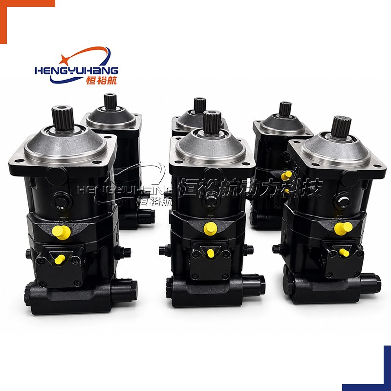
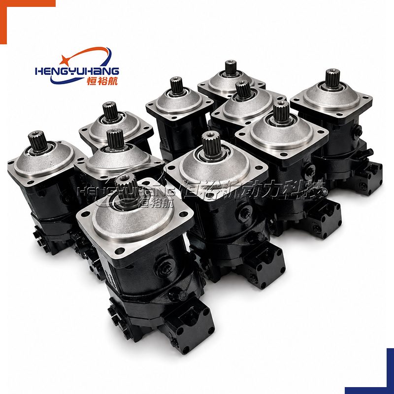
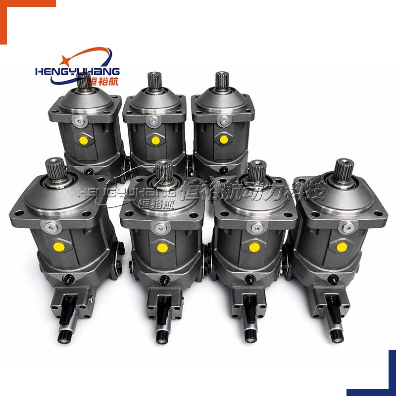
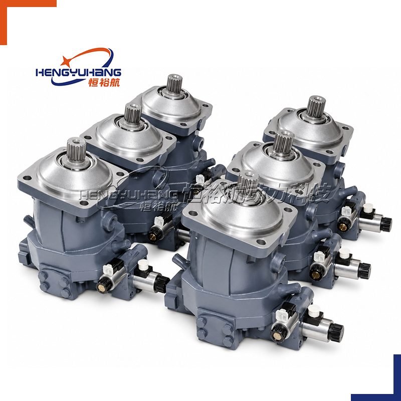
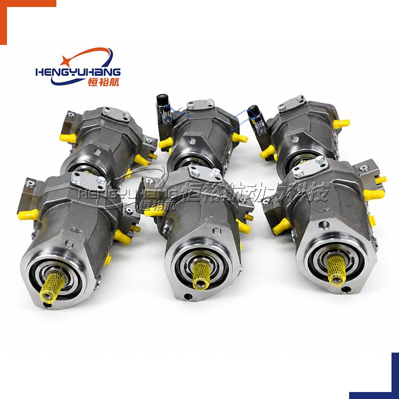
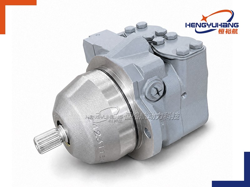
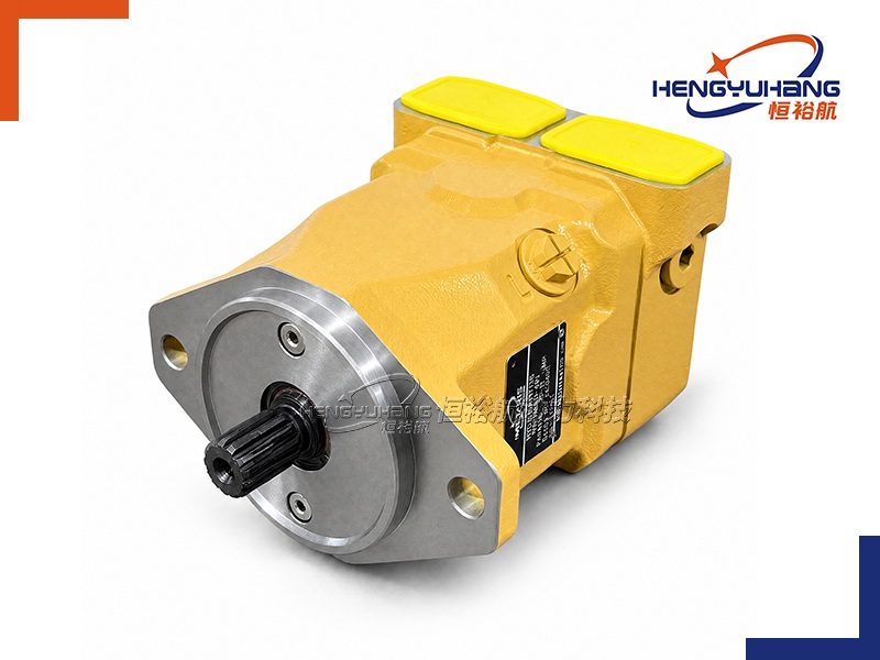
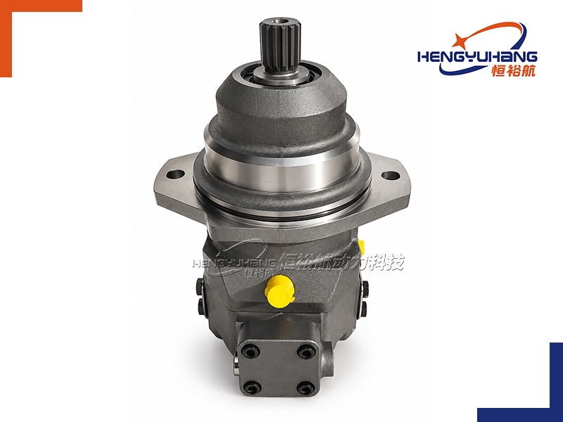
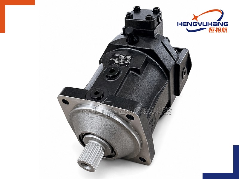
HENGYUHANG HYH6VM Series 65 And 71 Axial Piston Variable Motor
Engineered with heavy-duty bent-axis rotary group technology and standard ISO 3019-2 mounting flanges, the HENGYUHANG HYH6VM Series 65 and 71 variable displacement motor delivers up to 530 bar peak capability, high-speed swiveling down to zero displacement, and direct drop-in interchangeability for open and closed circuit hydrostatic transmissions.
| Applications
Designed for demanding mobile and industrial hydrostatic drivelines, the HYH6VM series drives wheeled excavator propel systems, crawler crane winches, rotary drilling rig rotary heads, concrete mixer drums, marine deck winches, and forestry processing heads. Its bent-axis geometry ensures exceptional starting torque, smooth crawl-speed stability, and high overspeed survivability.
| Key Technical Specifications
Product Model: HYH6VM Series 65 and Series 71 (Sizes 28, 55, 60, 80, 85, 107, 115, 140, 150, 160, 170, 200, 215, 280)
Brand Replacement: Bosch Rexroth A6VM Series 65 & 71 (OEM or tailored as requested)
Displacement: 0 to 28.1 / 54.8 / 62.0 / 80.3 / 85.2 / 106.7 / 115.6 / 140.2 / 152.1 / 160.2 / 171.8 / 200.0 / 216.5 / 280.1 cm³/rev (Swivelable to Vg = 0)
Rotation Direction: Bi-directional / Reversible (Viewed on drive shaft: W)
Speed Range: Up to 5,550 rpm at Vg max; up to 8,750 rpm at Vg < Vgx; up to 10,450 rpm at Vg = 0
Peak Pressure: Nominal 400 bar (Series 65) / 450 bar (Series 71); Maximum peak 450 bar (Size 28) / 500 bar (Size 280) / 530 bar (Sizes 55 to 215)
- Description
- Tecspecs
- Brand & Reference
- Download HENGYUHANG HYH6VM Series 65 And 71 Axial Piston Variable Motor PDF
- Send an Inquiry
| Overview of HENGYUHANG HYH6VM Series 65 and 71 Hydraulic Motors
The HENGYUHANG HYH6VM Series 65 and 71 is an industrial-grade axial piston variable displacement motor featuring bent-axis design for hydrostatic transmissions in both open and closed circuits. Built with standard 4-bolt ISO mounting flanges and high-capacity tapered roller bearings, the motor mounts directly to external machine gearboxes, winches, and reduction wheel drives. With a wide control ratio extending from maximum displacement down to complete zero-swivel (Vg = 0), the HYH6VM motor enables mobile equipment to transition seamlessly from high tractive breakaway torque to ultra-high roading speeds without auxiliary mechanical shifting. Series 71 incorporates optimized spherical valve plate geometry and rotary group micro-balancing, delivering exceptional creep-speed stability and vibration-free low-rpm operation required in high-precision crane hoisting and fine positioning operations.
| Dimension of HENGYUHANG HYH6VM Series 65 and 71 Hydraulic Motors
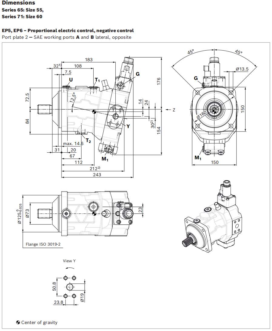
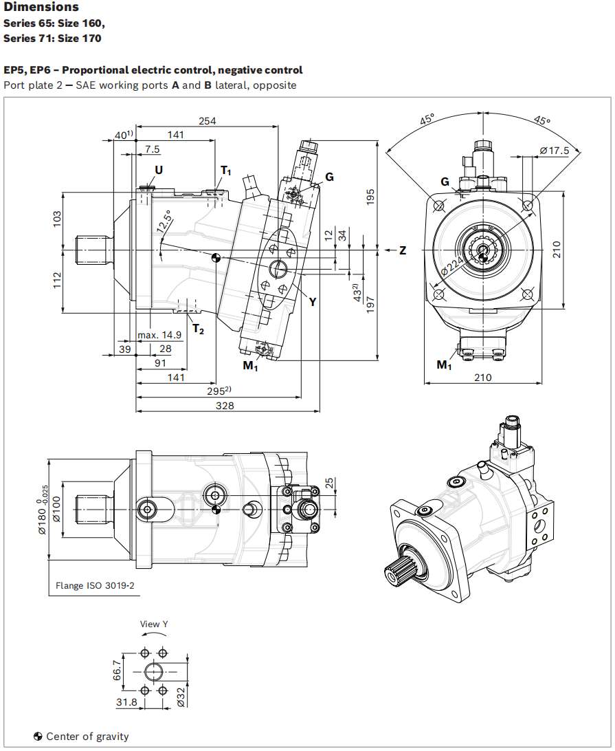
| Mechanical Mounting Interface Specifications
| Frame Size & Series | Mounting Flange (ISO 3019-2) | Pilot Centering Spigot (∅) |
|---|---|---|
| HYH6VM28 (s65) | ISO 100-4 | ∅100 −0.022/0 mm |
| HYH6VM55 (s65) | ISO 125-4 | ∅125 −0.025/0 mm |
| HYH6VM60 (s71) | ISO 125-4 | ∅125 −0.025/0 mm |
| HYH6VM80 (s65) | ISO 140-4 | ∅140 −0.025/0 mm |
| HYH6VM85 (s71) | ISO 140-4 | ∅140 −0.025/0 mm |
| HYH6VM107 (s65) | ISO 160-4 | ∅160 −0.025/0 mm |
| HYH6VM115 (s71) | ISO 160-4 | ∅160 −0.025/0 mm |
| HYH6VM140 (s65) | ISO 180-4 | ∅180 −0.025/0 mm |
| HYH6VM150 (s71) | ISO 180-4 | ∅180 −0.025/0 mm |
| HYH6VM160 (s65) | ISO 180-4 | ∅180 −0.025/0 mm |
| HYH6VM170 (s71) | ISO 180-4 | ∅180 −0.025/0 mm |
| HYH6VM200 (s65) | ISO 200-4 | ∅200 −0.029/0 mm |
| HYH6VM215 (s71) | ISO 200-4 | ∅200 −0.029/0 mm |
| HYH6VM280 (s71) | ISO 200-4 | ∅200 −0.029/0 mm |
| Frame Size & Series | Fastening Pitch Circle (PCD) / Bolt Holes | Standard DIN 5480 Splined Shaft | Standard ANSI B92.1a Splined Shaft | Working Port Flange Size (SAE J518) |
|---|---|---|---|---|
| HYH6VM28 (s65) | ∅125 mm / 4× ∅11 mm | W25×1.25×18×9g (Z5) | — | SAE 3/4" (Code 62 / 450 bar) |
| HYH6VM55 (s65) | ∅160 mm / 4× ∅14 mm | W30×2×14×9g (Z6) | 1 1/4" 14T 12/24DP (S7) | SAE 3/4" (Code 62 / 530 bar) |
| HYH6VM60 (s71) | ∅160 mm / 4× ∅14 mm | W35×2×16×9g (Z8) | 1 1/4" 14T 12/24DP (S7) | SAE 3/4" (Code 62 / 530 bar) |
| HYH6VM80 (s65) | ∅180 mm / 4× ∅18 mm | W35×2×16×9g (Z8) | 1 1/4" 14T 12/24DP (S7) | SAE 1" (Code 62 / 530 bar) |
| HYH6VM85 (s71) | ∅180 mm / 4× ∅18 mm | W40×2×18×9g (Z9) | 1 1/2" 17T 12/24DP (S9) | SAE 1" (Code 62 / 530 bar) |
| HYH6VM107 (s65) | ∅200 mm / 4× ∅18 mm | W40×2×18×9g (Z9) | 1 3/4" 13T 8/16DP (T1) | SAE 1" (Code 62 / 530 bar) |
| HYH6VM115 (s71) | ∅200 mm / 4× ∅18 mm | W40×2×18×9g (Z9) | 1 3/4" 13T 8/16DP (T1) | SAE 1" (Code 62 / 530 bar) |
| HYH6VM140 (s65) | ∅224 mm / 4× ∅22 mm | W45×2×21×9g (A1) | 1 3/4" 13T 8/16DP (T1) | SAE 1 1/4" (Code 62 / 530 bar) |
| HYH6VM150 (s71) | ∅224 mm / 4× ∅22 mm | W45×2×21×9g (A1) | 2" 15T 8/16DP (T2) | SAE 1 1/4" (Code 62 / 530 bar) |
| HYH6VM160 (s65) | ∅224 mm / 4× ∅22 mm | W45×2×21×9g (A1) | 1 3/4" 13T 8/16DP (T1) | SAE 1 1/4" (Code 62 / 530 bar) |
| HYH6VM170 (s71) | ∅224 mm / 4× ∅22 mm | W45×2×21×9g (A1) | 2" 15T 8/16DP (T2) | SAE 1 1/4" (Code 62 / 530 bar) |
| HYH6VM200 (s65) | ∅250 mm / 4× ∅22 mm | W50×2×24×9g (A2) | 2" 15T 8/16DP (T2) | SAE 1 1/4" (Code 62 / 530 bar) |
| HYH6VM215 (s71) | ∅250 mm / 4× ∅22 mm | W50×2×24×9g (A2) | 2" 15T 8/16DP (T2) | SAE 1 1/4" (Code 62 / 530 bar) |
| HYH6VM280 (s71) | ∅250 mm / 4× ∅22 mm | W60×2×28×9g (A4) | 2 1/4" 17T 8/16DP (T3) | SAE 1 1/2" (Code 62 / 500 bar) |
| Installation Specifications
| Mathematical Operating Characteristics
Inlet Flow Rate: qv = (Vg × n) / (1000 × ηv) [L/min]
Rotational Speed: n = (qv × 1000 × ηv) / Vg [rpm]
Output Torque: M = (Vg × Δp × ηhm) / (20 × π) [Nm]
Drive Power: P = (2π × M × n) / 60000 = (qv × Δp × ηt) / 600 [kW]
| Connection Port Identification & Standard Layout
| Port Identifier | Port Function / Description | Pressure Rating (pmax) | Applicable Metric Port Standard | Connection State |
|---|---|---|---|---|
| A, B | High-Pressure Working Ports | 450 bar / 500 bar / 530 bar | SAE J518 Code 62 (DIN 13 metric threads) | Must be connected |
| T1, T2 | Case Drain Fluid Ports | 3 bar continuous (10 bar peak) | ISO 6149 / DIN 3852 (M18×1.5 to M33×2) | One drain port connected to reservoir |
| X | Pilot Control Pressure Port | 100 bar (HP/HZ) / 3 bar (HA) | ISO 6149 (M14×1.5, 11.5 mm deep) | Connected for external pilot signal |
| G | Synchronous Control Port | 450 bar / 530 bar | ISO 6149 (M14×1.5, 11.5 mm deep) | Plugged during normal operation |
| M1 | Measuring Port Control Pressure | 450 bar / 530 bar | ISO 6149 (M14×1.5, 11.5 mm deep) | Plugged (diagnostic testing port) |
| MA, MB | Measuring Ports Working Pressure | 450 bar / 530 bar | ISO 6149 (M18×1.5 to M22×1.5) | Plugged (high-pressure test line) |
| U | Bearing Flushing Port | 3 bar | ISO 6149 (M14×1.5 to M18×1.5) | Connected for high thermal/vertical duty |
| Replacement Splined Shaft Interface Matrix
| Shaft Identifier | Standard & Dimensions | Typical Frame Sizes | Maximum Transmissible Torque Rating |
|---|---|---|---|
| Z5 | DIN 5480 W25×1.25×18×9g | HYH6VM28 | Full torque rating (179 Nm) |
| Z6 | DIN 5480 W30×2×14×9g | HYH6VM28, HYH6VM55 | Full torque rating (349 Nm) |
| Z8 | DIN 5480 W35×2×16×9g | HYH6VM55, HYH6VM60, HYH6VM80 | Full torque rating (509 Nm) |
| Z9 | DIN 5480 W40×2×18×9g | HYH6VM80, HYH6VM85, HYH6VM107, HYH6VM115 | Full torque rating (828 Nm) |
| A1 | DIN 5480 W45×2×21×9g | HYH6VM107, HYH6VM115, HYH6VM140, HYH6VM150, HYH6VM160, HYH6VM170 | Full torque rating (1,230 Nm) |
| A2 | DIN 5480 W50×2×24×9g | HYH6VM160, HYH6VM170, HYH6VM200, HYH6VM215 | Full torque rating (1,550 Nm) |
| A4 | DIN 5480 W60×2×28×9g | HYH6VM280 | Full torque rating (2,006 Nm) |
| S7 | ANSI B92.1a 1 1/4" 14T 12/24DP | HYH6VM55, HYH6VM60, HYH6VM80 | High-strength involute spline |
| S9 | ANSI B92.1a 1 1/2" 17T 12/24DP | HYH6VM85 | High-strength involute spline |
| T1 | ANSI B92.1a 1 3/4" 13T 8/16DP | HYH6VM107, HYH6VM115, HYH6VM140, HYH6VM160 | Heavy-duty mobile spline |
| T2 | ANSI B92.1a 2" 15T 8/16DP | HYH6VM150, HYH6VM170, HYH6VM200, HYH6VM215 | Extreme torque involute spline |
| T3 | ANSI B92.1a 2 1/4" 17T 8/16DP | HYH6VM280 | Extreme torque industrial spline |
Technical Specifications of HENGYUHANG HYH6VM Series (Series 65 & 71)
4.1 Series 65 Technical Performance Ratings (pₙₒₘ=400 bar)
| Technical Parameter | Unit | HYH6VM28 | HYH6VM55 | HYH6VM80 | HYH6VM107 | HYH6VM140 | HYH6VM160 | HYH6VM200 |
|---|---|---|---|---|---|---|---|---|
| Maximum Displacement (Vgₘₐₓ) | cm³/rev | 28.1 | 54.8 | 80.3 | 106.7 | 140.2 | 160.2 | 200.0 |
| Minimum Displacement (Vg min) | cm³/rev | 0 (Adjustable) | 0 (Adjustable) | 0 (Adjustable) | 0 (Adjustable) | 0 (Adjustable) | 0 (Adjustable) | 0 (Adjustable) |
| Intermediate Displacement (Vgx) | cm³/rev | 18.0 | 35.0 | 51.0 | 68.0 | 88.0 | 61.0 | 76.0 |
| Nominal Speed at Vgₘₐₓ (nₙₒₘ) | rpm | 5,550 | 4,450 | 3,900 | 3,550 | 3,250 | 3,100 | 2,900 |
| Max Permissible Speed (Vg<Vgx) (nₘₐₓ) | rpm | 8,750 | 7,000 | 6,150 | 5,600 | 5,150 | 4,900 | 4,600 |
| Limit Overspeed at Vg=0 (nmax0) | rpm | 10,450 | 8,350 | 7,350 | 6,300 | 5,750 | 5,500 | 5,100 |
| Max Inlet Inflow (qv max at nₙₒₘ) | L/min | 156 | 244 | 312 | 380 | 455 | 496 | 580 |
| Output Torque (Δp=400 bar at Vgₘₐₓ) | Nm | 179 | 349 | 509 | 681 | 891 | 1,019 | 1,273 |
| Mass Moment of Inertia (J_TW) | kg·m² | 0.0014 | 0.0042 | 0.0080 | 0.0127 | 0.0207 | 0.0253 | 0.0353 |
| Case Oil Volume (VV) | L | 0.50 | 0.75 | 1.20 | 1.50 | 1.80 | 2.40 | 2.70 |
| Dry Weight | kg | 16.0 | 28.0 | 36.0 | 46.0 | 61.0 | 62.0 | 78.0 |
4.2 Series 71 Technical Performance Ratings (pₙₒₘ=450 bar)
| Technical Parameter | Unit | HYH6VM60 | HYH6VM85 | HYH6VM115 | HYH6VM150 | HYH6VM170 | HYH6VM215 | HYH6VM280 |
|---|---|---|---|---|---|---|---|---|
| Maximum Displacement (Vgₘₐₓ) | cm³/rev | 62.0 | 85.2 | 115.6 | 152.1 | 171.8 | 216.5 | 280.1 |
| Minimum Displacement (Vg min) | cm³/rev | 0 (Adjustable) | 0 (Adjustable) | 0 (Adjustable) | 0 (Adjustable) | 0 (Adjustable) | 0 (Adjustable) | 0 (Adjustable) |
| Intermediate Displacement (Vgx) | cm³/rev | 37.0 | 51.0 | 69.0 | 91.0 | 65.0 | 130.0 | 118.0 |
| Nominal Speed at Vgₘₐₓ (nₙₒₘ) | rpm | 4,450 | 3,900 | 3,550 | 3,250 | 3,100 | 2,900 | 2,500 |
| Max Permissible Speed (Vg<Vgx) (nₘₐₓ) | rpm | 7,200 | 6,800 | 6,150 | 5,600 | 4,900 | 4,800 | 3,550 |
| Limit Overspeed at Vg=0 (nmax0) | rpm | 8,400 | 8,350 | 7,350 | 6,000 | 5,750 | 5,500 | 3,550 |
| Max Inlet Inflow (qv max at nₙₒₘ) | L/min | 275 | 332 | 410 | 494 | 533 | 628 | 700 |
| Output Torque (Δp=450 bar at Vgₘₐₓ) | Nm | 444 | 610 | 828 | 1,089 | 1,230 | 1,550 | 2,006 |
| Mass Moment of Inertia (J_TW) | kg·m² | 0.0043 | 0.0072 | 0.0110 | 0.0181 | 0.0213 | 0.0303 | 0.0479 |
| Case Oil Volume (VV) | L | 0.80 | 1.00 | 1.50 | 1.70 | 2.30 | 2.80 | 3.40 |
| Dry Weight | kg | 28.0 | 36.0 | 46.0 | 61.0 | 62.0 | 78.0 | 101.0 |
4.3 Operating Pressure Boundaries
| Pressure Parameter | Series 65 Ratings | Series 71 Ratings | Permissible Operational Duration / Condition |
|---|---|---|---|
| Nominal Pressure (pₙₒₘ) | 400 bar (5,800 psi) | 450 bar (6,500 psi) | Maximum continuous design working pressure |
| Maximum Pressure (pₘₐₓ) | 450 bar (Size 28) / 530 bar (Sizes 55–200) | 530 bar (Sizes 60–215) / 500 bar (Size 280) | Single operating event ≤10 s; total operating accumulation ≤50 hours |
| Summation Pressure (p_su) | 700 bar (10,150 psi) | 700 bar (10,150 psi) | Sum of simultaneous working port pressures (p_A + p_B) |
| Minimum High-Pressure Port Inflow | 25 bar (360 psi) | 25 bar (360 psi) | Prevents piston slipper liftoff and cavitation damage |
| Continuous Housing Drain Pressure | 2.0 bar (29 psi) | 2.0 bar (29 psi) | Maximum average pressure across shaft seal ring |
| Transient Housing Pressure Peak | 10.0 bar (145 psi) | 10.0 bar (145 psi) | Permissible instantaneous surge duration t<0.1 s |
4.4 Hydraulic Fluid Cleanliness & Viscosity Requirements
| Fluid Property | Specified Operational Range | Criteria & System Guidelines |
|---|---|---|
| Approved Hydraulic Fluids | Mineral oil HLP per DIN 51524 | Contact engineering for environmentally acceptable (HEES/HEPR) fluids |
| Optimum Viscosity Range (νₒₚₜ) | 16 to 36 mm²/s | Maximizes total hydraulic-mechanical and volumetric efficiency |
| Permissible Continuous Range | 10 to 400 mm²/s | Minimum short-term viscosity: ν_min=7 mm²/s (t≤3 min at p≤0.3×pₙₒₘ) |
| Cold Start Viscosity Limit | ≤1,600 mm²/s | t≤3 min at unloaded crawl speed (p≤50 bar, n≤1,000 rpm, ϑ≥−25 ∘C) |
| Operating Temperature Range | −25 ∘C to +103 ∘C (FKM Seals) | Maximum allowable circuit fluid temperature: +115 ∘C at work ports |
| Required Cleanliness Class | ISO 4406 Class 20/18/15 | At viscosity <10 mm²/s, fluid cleanliness must meet ISO 19/17/14 |
Advantages
High-Pressure Bent-Axis Rotary Group
Advanced bent-axis rotary geometry with spherical valve plate surfaces achieves total operating efficiencies exceeding 93%, withstanding continuous 400/450 bar working pressures and 530 bar peak shock loads.
Wide Swivel Range (Down to Vg=0)
Stepless displacement variability swivels completely down to zero displacement, enabling mobile vehicles to achieve rapid roading velocities, high breakaway tractive effort, and freewheeling capability without shifting gears.
Superior Creep-Speed Stability (Series 71)
Specially engineered rotary group tolerances and micro-contoured spherical valve timing in Series 71 deliver smooth, jerk-free low-rpm starting efficiency and pulsation-free creep performance for precision crane hoisting.
Extensive Modular Control Variety
Supports hydraulic proportional (HP), electric proportional (EP), two-point hydraulic/electric shift (HZ/EZ), automatic load-sensing high-pressure control (HA), and travel-speed related automatic control (DA).
Integrated Valve & Functional Options
Fully compatible with bolt-on counterbalance valves (BVD/BVE), integrated counterbalance valves (BVI), high-flow low-pressure flushing and boost valves, and contactless electronic speed sensors (DSA/DST).
Direct 1:1 OEM Bolt-In Interchangeability
Identical ISO 3019-2 4-bolt pilot spigots, DIN 5480 / ANSI splines, and SAE J518 Code 62 port locations allow direct drop-in replacement of Bosch Rexroth A6VM Series 65 and 71 units with zero piping or chassis modification.
| Cross Reference
6.1 Dimensional & Hydraulic Frame Mapping
| Rexroth Original Model | Series & Pressure | Max Displacement | Mounting Flange (ISO) | Standard Splined Shaft | HENGYUHANG Replacement Model |
| A6VM28.../65 | Series 65 (400 bar) | 28.1 cm³/rev | ISO 100-4 | W25×1.25 (Z5) | HYH6VM28 |
| A6VM55.../65 | Series 65 (400 bar) | 54.8 cm³/rev | ISO 125-4 | W30×2 (Z6) / 1 1/4" (S7) | HYH6VM55 |
| A6VM60.../71 | Series 71 (450 bar) | 62.0 cm³/rev | ISO 125-4 | W35×2 (Z8) / 1 1/4" (S7) | HYH6VM60 |
| A6VM80.../65 | Series 65 (400 bar) | 80.3 cm³/rev | ISO 140-4 | W35×2 (Z8) / 1 1/4" (S7) | HYH6VM80 |
| A6VM85.../71 | Series 71 (450 bar) | 85.2 cm³/rev | ISO 140-4 | W40×2 (Z9) / 1 1/2" (S9) | HYH6VM85 |
| A6VM107.../65 | Series 65 (400 bar) | 106.7 cm³/rev | ISO 160-4 | W40×2 (Z9) / 1 3/4" (T1) | HYH6VM107 |
| A6VM115.../71 | Series 71 (450 bar) | 115.6 cm³/rev | ISO 160-4 | W40×2 (Z9) / 1 3/4" (T1) | HYH6VM115 |
| A6VM140.../65 | Series 65 (400 bar) | 140.2 cm³/rev | ISO 180-4 | W45×2 (A1) / 1 3/4" (T1) | HYH6VM140 |
| A6VM150.../71 | Series 71 (450 bar) | 152.1 cm³/rev | ISO 180-4 | W45×2 (A1) / 2" (T2) | HYH6VM150 |
| A6VM160.../65 | Series 65 (400 bar) | 160.2 cm³/rev | ISO 180-4 | W45×2 (A1) / 1 3/4" (T1) | HYH6VM160 |
| A6VM170.../71 | Series 71 (450 bar) | 171.8 cm³/rev | ISO 180-4 | W45×2 (A1) / 2" (T2) | HYH6VM170 |
| A6VM200.../65 | Series 65 (400 bar) | 200.0 cm³/rev | ISO 200-4 | W50×2 (A2) / 2" (T2) | HYH6VM200 |
| A6VM215.../71 | Series 71 (450 bar) | 216.5 cm³/rev | ISO 200-4 | W50×2 (A2) / 2" (T2) | HYH6VM215 |
| A6VM280.../71 | Series 71 (450 bar) | 280.1 cm³/rev | ISO 200-4 | W60×2 (A4) / 2 1/4" (T3) | HYH6VM280 |
6.2 Control Mechanism Functional Cross-Reference
| Control Code | Control Category | Actuation Characteristic | Operational Drive Function |
| HP1 / HP2 | Hydraulic Proportional | Positive control (ΔpSt = 10 bar or 25 bar) | Stepless displacement increase proportional to pilot pressure |
| HP5 / HP6 | Hydraulic Proportional | Negative control (ΔpSt = 10 bar or 25 bar) | Motor rests at Vg max; pilot pressure swivels motor to Vg min |
| EP1 / EP2 | Electric Proportional | Positive control (U = 12 V or 24 V DC) | Microprocessor/joystick controlled stepless speed and torque regulation |
| EP5 / EP6 | Electric Proportional | Negative control (U = 12 V or 24 V DC) | High-speed electric swiveling with failsafe return to Vg max |
| HZ5 / HZ7 | Hydraulic Two-Point | Negative pilot control (p pilot ≥ 10 bar) | Classic two-speed travel drive shifting (Turtle/Rabbit mode) |
| EZ5 / EZ6 | Electric Two-Point | Negative solenoid control (12 V / 24 V DC) | Instant push-button high/low speed switching via DEUTSCH connector |
| HA1 / HA2 | High-Pressure Automatic | Positive pressure-related automatic control | Self-regulating load-adaptive motor (automatically swivels to Vg max under load) |
| DA0 / DA1 / DA2 | Speed-Related Automatic | Negative control coupled with hydraulic/electric travel valve | Automotive-style travel drive regulated by diesel engine tachometric pressure |
| Brand Replacement
Bosch Rexroth (Primary 1:1 direct drop-in replacement for A6VM Series 65 and Series 71 variable displacement motors)
Linde Hydraulics (HMV-02 Series bent-axis variable motors)
Danfoss / Sauer-Danfoss (Series 51 and Series 51-1 bent-axis variable displacement motors)
Parker Hannifin / Voac (V12 and V14 bent-axis variable displacement motors)
Eaton / Vickers variable displacement motor retrofits engineered upon request
| Applications
Wheeled Excavator & Loader Propel Transmissions: Drives multi-speed powershift gearboxes and axles for high tractive effort and rapid highway transit.
Mobile Crane & Crawler Crane Hoist Winches: High-torque low-speed smooth lifting paired with high-speed lowering at reduced displacement.
Rotary Drilling Rigs & Foundation Equipment: Power head drive motors requiring wide torque-speed envelopes and severe shock resistance.
Concrete Transit Mixer Drives: Smooth low-speed drum rotation with precise speed regulation during road transport and discharge.
Forestry Harvesters & Forwarders: All-terrain wheel drive and processing head feeding roller transmissions.
Marine Deck Winches & Offshore Mooring Capstans: Extreme weather-resistant variable drives delivering high holding torque and dynamic tensioning.
| Packaging & Shipping
| Why Choose Hengyuhang?
Direct Factory Precision Manufacturing & CNC Excellence:
Multi-Axis CNC Machining Infrastructure:
In-house precision machining centers, advanced spherical cup grinding lines, and automated honing cells process every motor housing, cylinder block, and valve plate under climate-controlled conditions.
Sub-Micron Micro-Finishing (Ra < 0.2 μm):
Critical dynamic friction pairs—including piston slipper pads, spherical cylinder block faces, and bi-metal valve plate running tracks—undergo super-finishing to ensure fluid-film hydro-dynamic equilibrium, minimal internal leakage, and zero micro-scuffing even under high operating temperatures.
Metallurgical Integrity & Thermal Hardening:
High-grade nodular ductile iron castings and hardened alloy piston assemblies withstand continuous 400/450 bar rated duty and 530 bar transient dynamic shock spikes without structural distortion or bore deformation.
100% Full-Cycle Multi-Parameter Factory Inspection & Digital Testing:
End-of-Line Automated Test Bench Validation:
Every assembled HYH6VM motor undergoes mandatory, computer-controlled testing simulating real-world crane hoist and excavator drive duty cycles.
High-Standard Performance Criteria:
Volumetric Efficiency Verification: Proven > 94% at full displacement under full working pressure, eliminating sluggish machine drive response.
Pressure Endurance Verification: 100% sustained high-pressure hold at 400/450 bar nominal and 530 bar peak with zero external seal weepage.
Case Drain Flow Measurement: Real-time monitoring ensures internal bypass flow remains strictly within engineering limits, protecting machine coolers from excess heat generation.
Dynamic Two-Speed Response: Millisecond-level tracking of swashplate shift response from Vg max down to Vg min under HP, HZ, EZ, and HA control modes, verifying smooth, hysteresis-free transition without machine jerk.
Full Traceability: Individual test data curves and quality inspection logs are archived per unit serial number before packaging.
Seamless 1:1 OEM Drop-In Interchangeability (True Plug-and-Play):
Exact Dimensional Match:
Standard 4-bolt ISO 3019-2 mounting flange pilot diameters (ISO 100-4, 125-4, 140-4, 160-4, 180-4, 200-4), bolt circle PCDs, and pilot depths correspond 1:1 to original Bosch Rexroth A6VM Series 65 and 71 specifications down to the millimeter.
Zero Piping or Chassis Rework:
Standard rear SAE ports (Port Plate 1), side opposite SAE ports (Port Plate 2), and counterbalance-ready ports (Port Plate 6/7/8) connect directly to existing high-pressure hose assemblies and gearbox brackets with zero pipe bending or adaptor refitting.
Drive Spline Conformity:
Precision DIN 5480 and ANSI B92.1a involute splines mesh seamlessly with OEM gearboxes, winches, and reduction hubs without spline binding, backlash vibration, or premature drive hub wear.
Flexible Engineering Customization & Rapid Prototyping:
Tailored Displacement Settings:
Factory-preset minimum displacement screws (Vg min) calibrated exactly to client gearbox speed requirements prior to shipment, saving field commissioning labor.
Custom Orifice & Shift Tuning:
Tailored internal shift damping orifices engineered to dampen shift shock in sensitive hydrostatic transmissions.
Agile OEM/ODM Solutions:
Experienced fluid power engineers provide rapid turnaround for customized port thread standards (Metric / SAE / BSPP), specialized shaft extensions, and integrated dual counterbalance/flushing valve blocks, backed by flexible, low-MOQ policies for trial batches.
Robust Supply Chain, Extensive Inventory & Fast Global Dispatch:
Strategic Component Buffering:
Continuous safety stocks of fully machined motor housings, finished bent-axis rotary groups, precision bearing kits, and modular EZ/HZ/HA pilot controllers maintained at the factory warehouse.
Rapid 48–72 Hour Dispatch:
Standard configurations and replacement units ship within 48 to 72 hours of order confirmation, eliminating costly mobile machinery downtime.
Global Multimodal Logistics:
Established partnerships with tier-1 international freight forwarders, supporting express courier (DHL, FedEx, UPS), air cargo, and door-to-door DDP ocean shipping with full customs handling.
12-Month Comprehensive Warranty & Dedicated Lifetime Technical Support:
Full-Protection Factory Warranty:
Comprehensive 12-month warranty covering any manufacturing or material defects with immediate replacement-part dispatch support.
24-Hour Drawing & Model Code Verification:
Dedicated technical desk reviews customer machine models, nameplates, port layouts, and dimensional drawings within 24 hours to guarantee zero ordering errors.
Direct Hydraulic Engineering Consultation:
Direct technical access to fluid power engineers for circuit troubleshooting, oil contamination analysis, flushing flow sizing, and replacement cross-referencing throughout the machine's entire operational lifecycle.
| Packaging Layer | Material Standard & Specification | Protection Level |
| Primary Shielding | Corrosion-inhibiting VCI foil wrap, moisture desiccants, and heavy-duty port thread plugs | Total isolation against ocean atmospheric moisture, rust, and contamination |
| Shock Absorption | Form-fitted high-density expanded polyethylene (EPE) foam cushioning enclosure | Absorbs multi-axis impact forces and prevents damage to pilot spigots and splines |
| Outer Enclosure | Heavy-duty ISPM-15 export-compliant non-fumigation engineered wooden crate | Rigid structural containment for global air cargo, ocean LCL/FCL, and multimodal transport |
| Logistics Options | Express Courier (DHL, FedEx, UPS), International Air Freight, Ocean Cargo (DDP / CIF) | Standard configurations dispatched in 48–72 hours; end-to-end milestone tracking |
HENGYUHANG Axial Piston Variable Motor HYH6VM Series 65 & 71
HENGYUHANG Axial Piston Variable Motor HYH6VM Series 65 and 71 is a heavy-duty, bent-axis variable displacement hydraulic motor engineered for demanding hydrostatic drives in both open and closed circuits. Built with spherical tapered piston rotary groups, the HYH6VM motor delivers high starting efficiency, massive output torque, exceptional reliability, and approved rotational speeds exceeding 10,000 rpm. Available across two advanced product series—Series 65 (standard nominal pressure 400 bar, sizes 28 to 200 cm³/rev) and Series 71 (high-pressure 450 bar rating with 9-piston rotary groups, sizes 60 to 280 cm³/rev for ultra-smooth low-speed crawl)—the HYH6VM Series is a direct dimensional, hydraulic, and functional drop-in replacement for OEM Bosch Rexroth A6VM Series 65 and Series 71 motors across mobile construction machinery, winch hoists, drilling rigs, and industrial transmissions.
Key Technical & Operational Features
Heavy-Duty Bent-Axis Architecture: Spherical tapered piston heads operating in a rigid cylinder block deliver unmatched mechanical-hydraulic efficiency, high starting torque under load, and extended service life.
High Pressure Ratings (Series 65 vs 71): Series 65 is rated for 400 bar nominal continuous pressure (peak up to 530 bar); Series 71 is rated for 450 bar nominal continuous pressure (peak up to 530 bar on sizes 60–215, 500 bar on size 280).
Outstanding Slow-Running Behavior (Series 71): Optimized 9-piston rotary group technology on Series 71 virtually eliminates torque pulsation and hesitation, providing exceptionally smooth, uniform rotation at crawl speeds.
Wide Control Range with Zero-Swivel Capability: Infinitely variable displacement swivels smoothly from maximum displacement (Vg max) all the way to zero (Vg = 0 cm³), allowing maximum vehicle travel speeds and gearbox freewheeling.
Approved for Extreme Rotational Speeds: Precision dynamic rotary balance allows operating speeds up to 5550 rpm at Vg max and overspeed capabilities up to 10450 rpm at zero displacement.
Standard ISO 3019-2 4-Bolt Flange: Robust 4-bolt pilot mounting flange (L4 to S4, pilot Ø100 mm to Ø200 mm) enables direct rigid bolting to machine chassis, reduction gearboxes, or bracket frames.
Versatile Valve Integration Options: Available with factory-mounted flushing and boost-pressure valves (calibrated 3.5 to 37 L/min) or mounted counterbalance valves (BVD20, BVD25, BVE25, BVD32, BVI) to prevent runaway on inclines.
Large Variety of Control Options: Fully compatible with hydraulic proportional (HP), electric proportional (EP), hydraulic two-point (HZ), electric two-point (EZ), automatic high-pressure related (HA), and speed-dependent automotive (DA) controls.
Heavy-Duty Industrial & Mobile Applications
The HENGYUHANG HYH6VM Series 65 and 71 variable displacement motors are extensively deployed in high-pressure mobile traction and heavy-duty industrial rotary drives:
Construction & Road Machinery: Wheel excavator travel drives, asphalt and concrete pavers, cold planers, soil compactors, vibratory rollers, and heavy motor graders.
Lifting & Material Handling: High-speed mobile crane hoisting winches, crawler crane boom derricking winches, tower crane slewing mechanisms, and shipboard deck cranes.
Drilling & Underground Mining: Rotary drilling rig power heads, continuous flight auger (CFA) drives, underground utility crawlers, coal mine roadheaders, and horizontal directional drill rigs.
Forestry & Agriculture Equipment: Tree feller bunchers, forestry forwarders, timber harvester processing heads, combine harvester header drives, and high-clearance self-propelled sprayers.
Technical Performance Matrix (OEM Benchmark Standard)
Series 65 (Nominal Pressure 400 bar, Sizes 28 to 200)
| Technical Parameter / Unit | Size 28 | Size 55 | Size 80 | Size 107 | Size 140 | Size 160 | Size 200 |
|---|---|---|---|---|---|---|---|
| Max Geometric Displacement Vg max [cm³] | 28.1 | 54.8 | 80.3 | 106.7 | 140.2 | 160.2 | 200.0 |
| Min Geometric Displacement Vg min [cm³] | 0 | 0 | 0 | 0 | 0 | 0 | 0 |
| Intermediate Swivel Displacement Vgx [cm³] | 18.0 | 35.0 | 51.0 | 68.0 | 88.0 | 61.0 | 76.0 |
| Nominal Continuous Pressure pnom [bar] | 400 | 400 | 400 | 400 | 400 | 400 | 400 |
| Maximum Peak Pressure pmax [bar] | 450 | 530 | 530 | 530 | 530 | 530 | 530 |
| Nominal Speed at Vg max (nnom) [rpm] | 5550 | 4450 | 3900 | 3550 | 3250 | 3100 | 2900 |
| Max Speed at Vg < Vgx (nmax) [rpm] | 8750 | 7000 | 6150 | 5600 | 5150 | 4900 | 4600 |
| Max Speed at Zero Swivel Vg = 0 (nmax) [rpm] | 10450 | 8350 | 7350 | 6300 | 5750 | 5500 | 5100 |
| Max Inlet Flow qv max (at nnom, Vg max) [L/min] | 156 | 244 | 312 | 380 | 455 | 496 | 580 |
| Theoretical Torque at Vg max (Δp = 400 bar) [Nm] | 179 | 349 | 509 | 681 | 891 | 1019 | 1273 |
| Rotary Stiffness Vg max to Vg/2 cmin [kNm/rad] | 6 | 10 | 16 | 21 | 34 | 35 | 44 |
| Rotary Stiffness Vg/2 to Vg = 0 cmin [kNm/rad] | 18 | 32 | 48 | 65 | 93 | 105 | 130 |
| Moment of Inertia of Rotary Group JTW [kg·m²] | 0.0014 | 0.0042 | 0.0080 | 0.0127 | 0.0207 | 0.0253 | 0.0353 |
| Case Fluid Volume [L] | 0.50 | 0.75 | 1.20 | 1.50 | 1.80 | 2.40 | 2.70 |
| Dry Weight (Approximate) [kg] | 16 | 28 | 36 | 46 | 61 | 62 | 78 |
Series 71 (High Pressure 450 bar, 9-Piston Group, Sizes 60 to 280)
| Technical Parameter / Unit | Size 60 | Size 85 | Size 115 | Size 150 | Size 170 | Size 215 | Size 280 |
|---|---|---|---|---|---|---|---|
| Max Geometric Displacement Vg max [cm³] | 62.0 | 85.2 | 115.6 | 152.1 | 171.8 | 216.5 | 280.1 |
| Min Geometric Displacement Vg min [cm³] | 0 | 0 | 0 | 0 | 0 | 0 | 0 |
| Intermediate Swivel Displacement Vgx [cm³] | 37.0 | 51.0 | 69.0 | 91.0 | 65.0 | 130.0 | 118.0 |
| Nominal Continuous Pressure pnom [bar] | 450 | 450 | 450 | 450 | 450 | 450 | 450 |
| Maximum Peak Pressure pmax [bar] | 530 | 530 | 530 | 530 | 530 | 530 | 500 |
| Nominal Speed at Vg max (nnom) [rpm] | 4450 | 3900 | 3550 | 3250 | 3100 | 2900 | 2500 |
| Max Speed at Vg < Vgx (nmax) [rpm] | 7200 | 6800 | 6150 | 5600 | 4900 | 4800 | 3550 |
| Max Speed at Zero Swivel Vg = 0 (nmax) [rpm] | 8400 | 8350 | 7350 | 6000 | 5750 | 5500 | 3550 |
| Max Inlet Flow qv max (at nnom, Vg max) [L/min] | 275 | 332 | 410 | 494 | 533 | 628 | 700 |
| Theoretical Torque at Vg max (Δp = 450 bar) [Nm] | 444 | 610 | 828 | 1089 | 1230 | 1550 | 2006 |
| Rotary Stiffness Vg max to Vg/2 cmin [kNm/rad] | 15 | 22 | 37 | 44 | 52 | 70 | 72 |
| Rotary Stiffness Vg/2 to Vg = 0 cmin [kNm/rad] | 45 | 68 | 104 | 124 | 156 | 196 | 209 |
| Moment of Inertia of Rotary Group JTW [kg·m²] | 0.0043 | 0.0072 | 0.0110 | 0.0181 | 0.0213 | 0.0303 | 0.0479 |
| Case Fluid Volume [L] | 0.80 | 1.00 | 1.50 | 1.70 | 2.30 | 2.80 | 3.40 |
| Dry Weight (Approximate) [kg] | 28 | 36 | 46 | 61 | 62 | 78 | 101 |
* Values apply within optimum hydraulic viscosity range νopt = 16 to 36 mm²/s using standard mineral oil fluids. Maximum peak pressure of 530 bar (500 bar on size 280) is valid up to 10 seconds per cycle (max 50 hours cumulative). Continuous zero-displacement operation requires minimum boost pressure to prevent cavitation.
Mechanical Installation Interface Specifications
Part 1: Standard ISO 3019-2 4-bolt mounting flange dimensions, centering pilot diameter, bolt hole pitch circle, and splined drive shafts.
| Frame Size (NG) | Flange Standard & Code | Centering Pilot Ø (ISO 3019-2) | Bolt Pattern & Pitch Circle | Primary Drive Shaft (DIN 5480) | Alternative Drive Shaft (ANSI / DIN) |
|---|---|---|---|---|---|
| HYH6VM028 (S65) | ISO 3019-2 (Code L4) | Ø100 mm (0 / -0.022 mm) | 4-bolt / Pitch Ø125 mm / 4x Ø11.0 mm | Code Z5: W25×1.25×18×9g (L=35 mm) | Code Z6: W30×2×14×9g (L=35 mm) |
| HYH6VM055 / 060 | ISO 3019-2 (Code M4) | Ø125 mm (0 / -0.025 mm) | 4-bolt / Pitch Ø160 mm / 4x Ø14.0 mm | Code Z6: W30×2×14×9g (L=35 mm) | Code Z8: W35×2×16×9g / Code S7: 1 1/4" 14T |
| HYH6VM080 / 085 | ISO 3019-2 (Code N4) | Ø140 mm (0 / -0.025 mm) | 4-bolt / Pitch Ø180 mm / 4x Ø18.0 mm | Code Z8: W35×2×16×9g (L=40 mm) | Code Z9: W40×2×18×9g / Code S9: 1 1/2" 17T |
| HYH6VM107 / 115 | ISO 3019-2 (Code P4) | Ø160 mm (0 / -0.025 mm) | 4-bolt / Pitch Ø200 mm / 4x Ø18.0 mm | Code Z9: W40×2×18×9g (L=45 mm) | Code A1: W45×2×21×9g / Code T1: 1 3/4" 13T |
| HYH6VM140 / 150 | ISO 3019-2 (Code R4) | Ø180 mm (0 / -0.025 mm) | 4-bolt / Pitch Ø224 mm / 4x Ø22.0 mm | Code A1: W45×2×21×9g (L=50 mm) | Code T1: 1 3/4" 13T / Code T2: 2.0" 15T |
| HYH6VM160 / 170 | ISO 3019-2 (Code R4) | Ø180 mm (0 / -0.025 mm) | 4-bolt / Pitch Ø224 mm / 4x Ø22.0 mm | Code A1: W45×2×21×9g (L=50 mm) | Code A2: W50×2×24×9g / Code T2: 2.0" 15T |
| HYH6VM200 / 215 | ISO 3019-2 (Code S4) | Ø200 mm (0 / -0.029 mm) | 4-bolt / Pitch Ø250 mm / 4x Ø22.0 mm | Code A2: W50×2×24×9g (L=55 mm) | Code T2: 2.0" 15T (ANSI B92.1a) |
| HYH6VM280 (S71) | ISO 3019-2 (Code S4) | Ø200 mm (0 / -0.029 mm) | 4-bolt / Pitch Ø250 mm / 4x Ø22.0 mm | Code A4: W60×2×28×9g (L=70 mm) | Code T3: 2 1/4" 17T (ANSI B92.1a) |
Fluid Connection & Port Configuration Specifications
Part 2: Hydraulic fluid connections across working lines A/B (SAE J518 Code 62), case drain ports T1/T2, synchronous control G, bearing flush U, pilot X, and test ports.
| Frame Size (NG) | Working Ports A & B (SAE J518) | Drain Ports T1, T2 (ISO 6149 / DIN) | Synchronous G / Bearing Flush U | Pilot Port X (HP, HZ, HA) | Pilot X1, X2 (DA0 Travel) | Gauge Ports M1 / MA, MB |
|---|---|---|---|---|---|---|
| HYH6VM028 (S65) | SAE 3/4 in (M10×1.5, 17 deep, pmax 450 bar) | T1, T2: M18×1.5 (12 deep, pmax 3 bar) | G: M14×1.5 / U: M16×1.5 | M14×1.5 (11.5 deep, pmax 100 bar) | 8B-ST (DIN 2353-CL, pmax 40 bar) | M1: M14×1.5 / MA,MB: – |
| HYH6VM055 / 060 | SAE 3/4 in (M10×1.5, 17 deep, pmax 530 bar) | T1: M22×1.5 / T2: M27×2 (pmax 3 bar) | G: M14×1.5 / U: M18×1.5 | M14×1.5 (11.5 deep, pmax 100 bar) | SDSC-L8×M12-F (pmax 40 bar) | M1: M14×1.5 / MA,MB: – |
| HYH6VM080 / 085 | SAE 1.0 in (M12×1.75, 17 deep, pmax 530 bar) | T1: M22×1.5 / T2: M27×2 (pmax 3 bar) | G: M14×1.5 / U: M18×1.5 | M14×1.5 (11.5 deep, pmax 100 bar) | SDSC-L8×M12-F (pmax 40 bar) | M1: M14×1.5 / MA,MB: M18×1.5 |
| HYH6VM107 / 115 | SAE 1.0 in (M12×1.75, 17 deep, pmax 530 bar) | T1: M27×2 / T2: M33×2 (pmax 3 bar) | G: M14×1.5 / U: M18×1.5 | M14×1.5 (11.5 deep, pmax 100 bar) | SDSC-L8×M12-F (pmax 40 bar) | M1: M14×1.5 / MA,MB: M18×1.5 |
| HYH6VM140 / 150 | SAE 1 1/4 in (M14×2, 19 deep, pmax 530 bar) | T1: M27×2 / T2: M33×2 (pmax 3 bar) | G: M14×1.5 / U: M22×1.5 | M14×1.5 (11.5 deep, pmax 100 bar) | SDSC-L8×M12-F (pmax 40 bar) | M1: M14×1.5 / MA,MB: M22×1.5 |
| HYH6VM160 / 170 | SAE 1 1/4 in (M14×2, 19 deep, pmax 530 bar) | T1: M27×2 / T2: M33×2 (pmax 3 bar) | G: M14×1.5 / U: M22×1.5 | M14×1.5 (11.5 deep, pmax 100 bar) | SDSC-L8×M12-F (pmax 40 bar) | M1: M14×1.5 / MA,MB: M22×1.5 |
| HYH6VM200 / 215 | SAE 1 1/4 in (M14×2, 19 deep, pmax 530 bar) | T1: M33×2 / T2: M42×2 (pmax 3 bar) | G: M14×1.5 / U: M22×1.5 | M14×1.5 (11.5 deep, pmax 100 bar) | SDSC-L8×M12-F (pmax 40 bar) | M1: M14×1.5 / MA,MB: M22×1.5 |
| HYH6VM280 (S71) | SAE 1 1/4 in (M14×2, 19 deep, pmax 500 bar) | T1: M42×2 / T2: M33×2 (pmax 3 bar) | G: M14×1.5 / U: M14×1.5 | M14×1.5 (11.5 deep, pmax 100 bar) | SDSC-L8×M12-F (DA7, pmax 40 bar) | M1: M14×1.5 / MA,MB: M14×1.5 |
Comprehensive Control Devices & Operating Characteristics
| Control Code | Operating Mode & Actuation | Functional Characteristics & Circuit Dynamics |
|---|---|---|
| HP1 / HP2 HP5 / HP6 | Proportional Control, Hydraulic (Positive / Negative Control) | Displacement is steplessly varied in direct proportion to hydraulic pilot pressure applied to port X. Positive control (HP1/HP2) increases displacement from Vg min to Vg max as pilot pressure rises; Negative control (HP5/HP6) swivels from Vg max down to Vg min with increasing pilot pressure. Control differential available in ΔpSt = 10 bar or 25 bar. Optionally combined with pressure cut-off D1. |
| EP1 / EP2 EP5 / EP6 | Proportional Control, Electric (12V / 24V DC Solenoid) | Stepless electronic control using a proportional solenoid. Positive control (EP1/EP2) increases displacement as electrical control current rises; Negative control (EP5/EP6) decreases displacement towards Vg min as current rises. Solenoid rated for 100% duty cycle, equipped with DEUTSCH DT04-2P connector. Control pressure is supplied internally from the operating high-pressure side. |
| HZ5 / HZ7 | Two-Point Control, Hydraulic (Negative Control) | Two-position switching motor: rest position at Vg max (maximum torque for hill climbing or heavy cutting). When pilot pressure pX ≥ 10–18 bar is applied to port X, the motor swivels rapidly to Vg min (high travel speed). HZ5 is standard on sizes 28, 140, 160, 200, 280; HZ7 is standard on sizes 55, 60, 80, 85, 107, 115. |
| EZ5 / EZ6 EZ7 / EZ8 | Two-Point Control, Electric (12V / 24V Switching Solenoid) | Direct electronic two-position switching via on/off solenoid valve without external hydraulic pilot lines. De-energized = Vg max; Energized = Vg min. EZ5/EZ6 (12V/24V) standard on sizes 28, 140, 160, 200, 280; EZ7/EZ8 (12V/24V) standard on sizes 55, 60, 80, 85, 107, 115. Requires high-pressure differential Δp ≥ 30 bar. |
| HA1 / HA2 HA1T / HA2T | Automatic High-Pressure Control (Load-Dependent Swiveling) | Load-sensing automatic down-swiveling: when working pressure rises due to increased vehicle traction resistance, the motor automatically swivels from Vg min to Vg max. HA1: minimum pressure increase Δp ≤ 10 bar; HA2: pressure increase Δp = 100 bar for smooth acceleration. Versions HA1T/HA2T include hydraulic remote proportional override T3. |
| DA0 / DA1 / DA2 DA7 | Automatic Speed-Related Control (Automotive Drive Hydrostat) | Speed-sensing negative control driven by engine speed pilot pressure from an A4VG/DA pump. DA0: with hydraulic travel direction valve (pilot ratio pSt/pHD = 5/100). DA1/DA2: with electric travel direction valve (12V/24V) and electric Vg max override. DA7: specialized for size 280 with pilot ratio 3/100. |
HENGYUHANG HYH6VM Series 65 & 71 Ordering Code Structure
| Pos. | Code Segment | Available Options | Description & Engineering Specifications |
|---|---|---|---|
| 01 | Axial Piston Unit | HYH6V | Bent-axis variable displacement hydraulic motor, high-pressure design |
| 02 | Operating Mode | M | Motor, open and closed hydrostatic circuits |
| 03 | Nominal Size (NG) | 028 to 200 (S65) 060 to 280 (S71) | Series 65: 028, 055, 080, 107, 140, 160, 200 cm³/rev (400 bar) Series 71: 060, 085, 115, 150, 170, 215, 280 cm³/rev (450 bar, 9-piston) |
| 04 | Control Devices | HP1 / HP2 HP5 / HP6 EP1 / EP2 EP5 / EP6 HZ5 / HZ7 EZ5 / EZ6 EZ7 / EZ8 HA1 / HA2 DA0 / DA1 / DA2 / DA7 | Proportional control, hydraulic, positive control (ΔpSt = 10 / 25 bar) Proportional control, hydraulic, negative control (ΔpSt = 10 / 25 bar) Proportional control, electric, positive control (12V / 24V DC) Proportional control, electric, negative control (12V / 24V DC) Two-point control, hydraulic, negative control (HZ5: 28/140–280; HZ7: 55–115) Two-point control, electric 12V / 24V DC (sizes 28, 140, 160, 200, 280) Two-point control, electric 12V / 24V DC (sizes 55, 60, 80, 85, 107, 115) Automatic high-pressure related control (HA1: Δp≤10 bar; HA2: Δp=100 bar) Automatic speed-related control with travel direction valve |
| 05 | Pressure Control / Override | 00 D1 T3 U1 / U2 R1 / R2 | Without pressure control or override Pressure control fixed setting (for HP5, HP6, EP5, EP6) Hydraulic remote proportional override (for HA1, HA2 controls) Electric two-point override 12V / 24V DC (for HA1, HA2) Electric override with electric travel direction valve 12V / 24V DC |
| 06 | Solenoid Connector | 0 P | Without electrical connector (for purely hydraulic controls) DEUTSCH molded 2-pin connector DT04-2P without suppressor diode |
| 07–08 | Sensors & Functions | 0 N | Standard without swivel angle sensor or neutral switch Integrated neutral position switch (available on sizes 80 to 215) |
| 09 | Stroking Time Damping | 0 1 4 7 | Without damping (standard with HP and EP) Damping orifice for HP, EP, HZ, EZ, HA with counterbalance valves One-sided damping in inlet to large stroking chamber (for HA control) One-sided damping in outlet from large stroking chamber (for DA control) |
| 10 | Displacement Setting | A, B, C, D E, F, G, H J, K, L, M | Without Vg max screw, Vg min stop screw: Short (0-adjustable), Moderate, Long, Extra long Short Vg max screw, Vg min stop screw: Short (0-adjustable), Moderate, Long, Extra long Medium Vg max screw, Vg min stop screw: Short (0-adjustable), Moderate, Long, Extra long |
| 11 | Series Index | 65 71 | Series 6, Index 5 (nominal pressure 400 bar, sizes 28–200) Series 7, Index 1 (nominal pressure 450 bar, 9-piston, sizes 60–280) |
| 12 | Threads & Ports | M N | Metric ports based on ISO 6149 with O-ring seal, DIN 13 fastening threads (sizes 55–280) Metric ports based on DIN 3852 with profile seal, DIN 13 fastening threads (size 28) |
| 13 | Direction of Rotation | W | Bi-directional (reversible, viewed on drive shaft) |
| 14 | Sealing Material | V | FKM (Fluorocarbon rubber / Viton seals, high-temperature rating) |
| 15 | Drive Shaft Bearing | 0 | Standard heavy-duty tapered roller bearing assembly |
| 16 | Mounting Flange | L4 M4 N4 P4 R4 S4 | ISO 3019-2 100-4 (4-bolt, size 28) ISO 3019-2 125-4 (4-bolt, sizes 55, 60) ISO 3019-2 140-4 (4-bolt, sizes 80, 85) ISO 3019-2 160-4 (4-bolt, sizes 107, 115) ISO 3019-2 180-4 (4-bolt, sizes 140, 150, 160, 170) ISO 3019-2 200-4 (4-bolt, sizes 200, 215, 280) |
| 17 | Drive Shaft (DIN / ANSI) | Z5 / Z6 Z6 / Z8 / S7 Z8 / Z9 / S9 Z9 / A1 / T1 A1 / A2 / T2 A2 / T2 A4 / T3 | DIN W25×1.25 / W30×2 (size 28) DIN W30×2 / W35×2 / ANSI 1 1/4" 14T (sizes 55, 60) DIN W35×2 / W40×2 / ANSI 1 1/2" 17T (sizes 80, 85) DIN W40×2 / W45×2 / ANSI 1 3/4" 13T (sizes 107, 115) DIN W45×2 / W50×2 / ANSI 2.0" 15T (sizes 140, 150, 160, 170) DIN W50×2 / ANSI 2.0" 15T (sizes 200, 215) DIN W60×2 / ANSI 2 1/4" 17T (size 280) |
| 18 | Working Ports A & B | 1 2 4 6 7 / 8 / 5 / 9 | SAE working ports A and B at rear (all sizes) SAE working ports A and B lateral, opposite (all sizes) SAE working ports at rear, with lateral measuring ports MA, MB SAE working ports at bottom, with integrated counterbalance valve BVI Port plates configured for mounted counterbalance valves BVD20, BVD25, BVE25, BVD32 |
| 19 | Valves & Flushing | 0 W Y A to M V | Without valve block With mounted BVD / BVE counterbalance valve With integrated brake release valve (only with port plate 6) With mounted flushing and boost-pressure valve (fixed orifice 3.5 to 37 L/min) With adjustable flushing valve (0 to 60 L/min, size 280) |
| 20 | Speed Sensor | 0 W C / E | Without speed sensor Prepared for speed sensor DSA/20 or DST Speed sensor DSA/20 mounted (C) / Speed sensor DST mounted (E) |
| 21 | Execution Version | 0 Y / S | Standard factory version Special installation variant (Y) / Customer-specific special build (S) |
Example Standard Order Codes: HYH6VM107HZ7000001A/65MWV0P4Z9100-0 (Series 65, Size 107, HZ7 Control, 400 bar, Splined Shaft W40×2, Rear Ports) or HYH6VM115EP2000001A/71MWV0P4Z9200-0P (Series 71, Size 115, EP2 Electric Control, 450 bar, 9-Piston, Side Ports).
Direct Interchangeability & OEM Cross-Reference Matrix
HENGYUHANG HYH6VM Series 65 & 71 variable displacement hydraulic motors are 100% physically and hydraulically interchangeable with OEM Bosch Rexroth A6VM Series 65 and 71 units, matching standard ISO 4-bolt pilot diameters, DIN/SAE drive shaft splines, port centerlines, and control curves:
| OEM Rexroth Model Code | HENGYUHANG Replacement Code | Series & Size | Control Option | Shaft & Flange | Interchangeability |
|---|---|---|---|---|---|
| A6VM028HZ5000001A/65NWV0L4Z5100-0 | HYH6VM028HZ5000001A/65NWV0L4Z5100-0 | Series 65, 28 cm³ | HZ5 Two-Point Hyd. | W25×1.25, ISO Ø100 | 100% Drop-In |
| A6VM055HZ7000001A/65MWV0M4Z6200-0 | HYH6VM055HZ7000001A/65MWV0M4Z6200-0 | Series 65, 55 cm³ | HZ7 Two-Point Hyd. | W30×2, ISO Ø125 | 100% Drop-In |
| A6VM060EP2000001A/71MWV0M4Z8200-0P | HYH6VM060EP2000001A/71MWV0M4Z8200-0P | Series 71, 62 cm³ (450 bar) | EP2 24V Prop. Elec. | W35×2, ISO Ø125 | 100% Drop-In |
| A6VM080HA2T30001A/65MWV0N4Z8100-0 | HYH6VM080HA2T30001A/65MWV0N4Z8100-0 | Series 65, 80 cm³ | HA2 Automatic + T3 | W35×2, ISO Ø140 | 100% Drop-In |
| A6VM085HZ7000001A/71MWV0N4Z9100-0 | HYH6VM085HZ7000001A/71MWV0N4Z9100-0 | Series 71, 85 cm³ (450 bar) | HZ7 Two-Point Hyd. | W40×2, ISO Ø140 | 100% Drop-In |
| A6VM107HZ7000001A/65MWV0P4Z9100-0 | HYH6VM107HZ7000001A/65MWV0P4Z9100-0 | Series 65, 107 cm³ | HZ7 Two-Point Hyd. | W40×2, ISO Ø160 | 100% Drop-In |
| A6VM115EP2000001A/71MWV0P4A1200-0P | HYH6VM115EP2000001A/71MWV0P4A1200-0P | Series 71, 115 cm³ (450 bar) | EP2 24V Prop. Elec. | W45×2, ISO Ø160 | 100% Drop-In |
| A6VM140HZ5000001A/65MWV0R4A1200-0 | HYH6VM140HZ5000001A/65MWV0R4A1200-0 | Series 65, 140 cm³ | HZ5 Two-Point Hyd. | W45×2, ISO Ø180 | 100% Drop-In |
| A6VM160EP2000001A/65MWV0R4A1100-0P | HYH6VM160EP2000001A/65MWV0R4A1100-0P | Series 65, 160 cm³ | EP2 24V Prop. Elec. | W45×2, ISO Ø180 | 100% Drop-In |
| A6VM170HZ5000001A/71MWV0R4A2200-0 | HYH6VM170HZ5000001A/71MWV0R4A2200-0 | Series 71, 172 cm³ (450 bar) | HZ5 Two-Point Hyd. | W50×2, ISO Ø180 | 100% Drop-In |
| A6VM200HZ5000001A/65MWV0S4A2200-0 | HYH6VM200HZ5000001A/65MWV0S4A2200-0 | Series 65, 200 cm³ | HZ5 Two-Point Hyd. | W50×2, ISO Ø200 | 100% Drop-In |
| A6VM215EP2000001A/71MWV0S4A2100-0P | HYH6VM215EP2000001A/71MWV0S4A2100-0P | Series 71, 216 cm³ (450 bar) | EP2 24V Prop. Elec. | W50×2, ISO Ø200 | 100% Drop-In |
| A6VM280HZ5000001A/71MWV0S4A4100-0 | HYH6VM280HZ5000001A/71MWV0S4A4100-0 | Series 71, 280 cm³ (450 bar) | HZ5 Two-Point Hyd. | W60×2, ISO Ø200 | 100% Drop-In |
Hydraulic Commissioning & Installation Guidelines
1. Initial Priming & Case Deaeration: Prior to initial start-up, the motor housing must be completely filled with clean, filtered hydraulic fluid via the uppermost drain port (T1 or T2) and thoroughly deaerated. Operating with an empty or partially filled housing will lead to instantaneous catastrophic seizure of the spherical cylinder block and drive shaft bearings.
2. Housing Drain Line Routing: The case drain line must be plumbed directly from the highest drain port back to the reservoir without restrictive check valves, shut-off valves, or undersized pipework. Housing pressure must not exceed 2.0 bar continuous (maximum surge peak ≤ 3.0 bar). Elevated case pressure significantly degrades radial shaft seal life and shifts the control pressure threshold of HP, HA, and DA regulators.
3. Low-Pressure Cavitation Prevention at Zero Swivel: When swiveling the motor to zero displacement (Vg = 0 cm³) during vehicle coasting, high-speed travel, or winch lowering, adequate boost pressure (low-pressure line pHD ≥ 10–14 bar abs) must be continuously maintained at the inlet working port to prevent cavitation, piston slipper lift-off, and rotary group separation.
4. Fluid Cleanliness & Filtration: Maintain fluid cleanliness class according to ISO 4406 at 20/18/15 or cleaner (at temperatures above 80 °C or low viscosity < 10 mm²/s, maintain 19/17/14). Utilize pressure or return line filters with β10 ≥ 100.
5. Counterbalance & Flushing Valve Selection: In closed circuits, always verify that the cracking pressure of the mounted flushing valve (16 bar fixed) is harmonized with the main pump charge relief valve, and confirm that counterbalance valve brake spool response times align with mechanical parking brake disengagement.
Data Verification & Technical Notes
Reference Benchmark Datasheet: Bosch Rexroth AG Technical Datasheet RE 91610 (Edition: 2025-01-29), Pages 1–105 (Axial Piston Variable Motor A6VM Series 65 and 71).
Quality Guarantee & Dynamic Testing: Every HENGYUHANG HYH6VM Series 65 and 71 motor is dynamically tested on computerized load benches for full swiveling angle linearity, high-speed stability up to 7000+ rpm, volumetric efficiency, starting torque, and case leakage under 400/450 bar continuous pressure before delivery.
Custom Engineering & Modifications: HENGYUHANG provides custom displacement stop limits (Vg max and Vg min screws), special shaft splines, neutral position indicator switches, integrated speed sensors (DSA/20, DST), and custom valve blocks tailored to specific machine serial numbers.
SEO Meta Title: HYH6VM Series 65 & 71 Axial Piston Variable Motor | Rexroth A6VM Replacement | Hengyuhang
SEO Meta Keywords: HYH6VM, A6VM series 65, A6VM series 71, axial piston variable motor, A6VM55, A6VM80, A6VM107, A6VM140, A6VM160, A6VM200, A6VM280, Rexroth A6VM replacement, bent axis motor, hydraulic travel motor, winch motor, Hengyuhang hydraulic
SEO Meta Description: Premium HENGYUHANG HYH6VM Series 65 & 71 axial piston variable displacement hydraulic motors. Direct replacement for Bosch Rexroth A6VM Series 65 and 71 (sizes 28 to 280). Nominal pressure 400/450 bar, peak up to 530 bar, bent-axis design, 9-piston rotary group, HP, EP, HZ, EZ, HA, DA controls.
Series 65 (Nominal Pressure 400 bar, Sizes 28 to 200)
| Technical Parameter / Unit | Size 28 | Size 55 | Size 80 | Size 107 | Size 140 | Size 160 | Size 200 |
|---|---|---|---|---|---|---|---|
| Max Geometric Displacement Vg max [cm³] | 28.1 | 54.8 | 80.3 | 106.7 | 140.2 | 160.2 | 200.0 |
| Min Geometric Displacement Vg min [cm³] | 0 | 0 | 0 | 0 | 0 | 0 | 0 |
| Intermediate Swivel Displacement Vgx [cm³] | 18.0 | 35.0 | 51.0 | 68.0 | 88.0 | 61.0 | 76.0 |
| Nominal Continuous Pressure pnom [bar] | 400 | 400 | 400 | 400 | 400 | 400 | 400 |
| Maximum Peak Pressure pmax [bar] | 450 | 530 | 530 | 530 | 530 | 530 | 530 |
| Nominal Speed at Vg max (nnom) [rpm] | 5550 | 4450 | 3900 | 3550 | 3250 | 3100 | 2900 |
| Max Speed at Vg < Vgx (nmax) [rpm] | 8750 | 7000 | 6150 | 5600 | 5150 | 4900 | 4600 |
| Max Speed at Zero Swivel Vg = 0 (nmax) [rpm] | 10450 | 8350 | 7350 | 6300 | 5750 | 5500 | 5100 |
| Max Inlet Flow qv max (at nnom, Vg max) [L/min] | 156 | 244 | 312 | 380 | 455 | 496 | 580 |
| Theoretical Torque at Vg max (Δp = 400 bar) [Nm] | 179 | 349 | 509 | 681 | 891 | 1019 | 1273 |
| Rotary Stiffness Vg max to Vg/2 cmin [kNm/rad] | 6 | 10 | 16 | 21 | 34 | 35 | 44 |
| Rotary Stiffness Vg/2 to Vg = 0 cmin [kNm/rad] | 18 | 32 | 48 | 65 | 93 | 105 | 130 |
| Moment of Inertia of Rotary Group JTW [kg·m²] | 0.0014 | 0.0042 | 0.0080 | 0.0127 | 0.0207 | 0.0253 | 0.0353 |
| Case Fluid Volume [L] | 0.50 | 0.75 | 1.20 | 1.50 | 1.80 | 2.40 | 2.70 |
| Dry Weight (Approximate) [kg] | 16 | 28 | 36 | 46 | 61 | 62 | 78 |
Series 71 (High Pressure 450 bar, 9-Piston Group, Sizes 60 to 280)
| Technical Parameter / Unit | Size 60 | Size 85 | Size 115 | Size 150 | Size 170 | Size 215 | Size 280 |
|---|---|---|---|---|---|---|---|
| Max Geometric Displacement Vg max [cm³] | 62.0 | 85.2 | 115.6 | 152.1 | 171.8 | 216.5 | 280.1 |
| Min Geometric Displacement Vg min [cm³] | 0 | 0 | 0 | 0 | 0 | 0 | 0 |
| Intermediate Swivel Displacement Vgx [cm³] | 37.0 | 51.0 | 69.0 | 91.0 | 65.0 | 130.0 | 118.0 |
| Nominal Continuous Pressure pnom [bar] | 450 | 450 | 450 | 450 | 450 | 450 | 450 |
| Maximum Peak Pressure pmax [bar] | 530 | 530 | 530 | 530 | 530 | 530 | 500 |
| Nominal Speed at Vg max (nnom) [rpm] | 4450 | 3900 | 3550 | 3250 | 3100 | 2900 | 2500 |
| Max Speed at Vg < Vgx (nmax) [rpm] | 7200 | 6800 | 6150 | 5600 | 4900 | 4800 | 3550 |
| Max Speed at Zero Swivel Vg = 0 (nmax) [rpm] | 8400 | 8350 | 7350 | 6000 | 5750 | 5500 | 3550 |
| Max Inlet Flow qv max (at nnom, Vg max) [L/min] | 275 | 332 | 410 | 494 | 533 | 628 | 700 |
| Theoretical Torque at Vg max (Δp = 450 bar) [Nm] | 444 | 610 | 828 | 1089 | 1230 | 1550 | 2006 |
| Rotary Stiffness Vg max to Vg/2 cmin [kNm/rad] | 15 | 22 | 37 | 44 | 52 | 70 | 72 |
| Rotary Stiffness Vg/2 to Vg = 0 cmin [kNm/rad] | 45 | 68 | 104 | 124 | 156 | 196 | 209 |
| Moment of Inertia of Rotary Group JTW [kg·m²] | 0.0043 | 0.0072 | 0.0110 | 0.0181 | 0.0213 | 0.0303 | 0.0479 |
| Case Fluid Volume [L] | 0.80 | 1.00 | 1.50 | 1.70 | 2.30 | 2.80 | 3.40 |
| Dry Weight (Approximate) [kg] | 28 | 36 | 46 | 61 | 62 | 78 | 101 |
| Pos. | Code Segment | Available Options | Description & Engineering Specifications |
|---|---|---|---|
| 01 | Axial Piston Unit | HYH6V | Bent-axis variable displacement hydraulic motor, high-pressure design |
| 02 | Operating Mode | M | Motor, open and closed hydrostatic circuits |
| 03 | Nominal Size (NG) | 028 to 200 (S65) 060 to 280 (S71) | Series 65: 028, 055, 080, 107, 140, 160, 200 cm³/rev (400 bar) Series 71: 060, 085, 115, 150, 170, 215, 280 cm³/rev (450 bar, 9-piston) |
| 04 | Control Devices | HP1 / HP2 HP5 / HP6 EP1 / EP2 EP5 / EP6 HZ5 / HZ7 EZ5 / EZ6 EZ7 / EZ8 HA1 / HA2 DA0 / DA1 / DA2 / DA7 | Proportional control, hydraulic, positive control (ΔpSt = 10 / 25 bar) Proportional control, hydraulic, negative control (ΔpSt = 10 / 25 bar) Proportional control, electric, positive control (12V / 24V DC) Proportional control, electric, negative control (12V / 24V DC) Two-point control, hydraulic, negative control (HZ5: 28/140–280; HZ7: 55–115) Two-point control, electric 12V / 24V DC (sizes 28, 140, 160, 200, 280) Two-point control, electric 12V / 24V DC (sizes 55, 60, 80, 85, 107, 115) Automatic high-pressure related control (HA1: Δp≤10 bar; HA2: Δp=100 bar) Automatic speed-related control with travel direction valve |
| 05 | Pressure Control / Override | 00 D1 T3 U1 / U2 R1 / R2 | Without pressure control or override Pressure control fixed setting (for HP5, HP6, EP5, EP6) Hydraulic remote proportional override (for HA1, HA2 controls) Electric two-point override 12V / 24V DC (for HA1, HA2) Electric override with electric travel direction valve 12V / 24V DC |
| 06 | Solenoid Connector | 0 P | Without electrical connector (for purely hydraulic controls) DEUTSCH molded 2-pin connector DT04-2P without suppressor diode |
| 07–08 | Sensors & Functions | 0 N | Standard without swivel angle sensor or neutral switch Integrated neutral position switch (available on sizes 80 to 215) |
| 09 | Stroking Time Damping | 0 1 4 7 | Without damping (standard with HP and EP) Damping orifice for HP, EP, HZ, EZ, HA with counterbalance valves One-sided damping in inlet to large stroking chamber (for HA control) One-sided damping in outlet from large stroking chamber (for DA control) |
| 10 | Displacement Setting | A, B, C, D E, F, G, H J, K, L, M | Without Vg max screw, Vg min stop screw: Short (0-adjustable), Moderate, Long, Extra long Short Vg max screw, Vg min stop screw: Short (0-adjustable), Moderate, Long, Extra long Medium Vg max screw, Vg min stop screw: Short (0-adjustable), Moderate, Long, Extra long |
| 11 | Series Index | 65 71 | Series 6, Index 5 (nominal pressure 400 bar, sizes 28–200) Series 7, Index 1 (nominal pressure 450 bar, 9-piston, sizes 60–280) |
| 12 | Threads & Ports | M N | Metric ports based on ISO 6149 with O-ring seal, DIN 13 fastening threads (sizes 55–280) Metric ports based on DIN 3852 with profile seal, DIN 13 fastening threads (size 28) |
| 13 | Direction of Rotation | W | Bi-directional (reversible, viewed on drive shaft) |
| 14 | Sealing Material | V | FKM (Fluorocarbon rubber / Viton seals, high-temperature rating) |
| 15 | Drive Shaft Bearing | 0 | Standard heavy-duty tapered roller bearing assembly |
| 16 | Mounting Flange | L4 M4 N4 P4 R4 S4 | ISO 3019-2 100-4 (4-bolt, size 28) ISO 3019-2 125-4 (4-bolt, sizes 55, 60) ISO 3019-2 140-4 (4-bolt, sizes 80, 85) ISO 3019-2 160-4 (4-bolt, sizes 107, 115) ISO 3019-2 180-4 (4-bolt, sizes 140, 150, 160, 170) ISO 3019-2 200-4 (4-bolt, sizes 200, 215, 280) |
| 17 | Drive Shaft (DIN / ANSI) | Z5 / Z6 Z6 / Z8 / S7 Z8 / Z9 / S9 Z9 / A1 / T1 A1 / A2 / T2 A2 / T2 A4 / T3 | DIN W25×1.25 / W30×2 (size 28) DIN W30×2 / W35×2 / ANSI 1 1/4" 14T (sizes 55, 60) DIN W35×2 / W40×2 / ANSI 1 1/2" 17T (sizes 80, 85) DIN W40×2 / W45×2 / ANSI 1 3/4" 13T (sizes 107, 115) DIN W45×2 / W50×2 / ANSI 2.0" 15T (sizes 140, 150, 160, 170) DIN W50×2 / ANSI 2.0" 15T (sizes 200, 215) DIN W60×2 / ANSI 2 1/4" 17T (size 280) |
| 18 | Working Ports A & B | 1 2 4 6 7 / 8 / 5 / 9 | SAE working ports A and B at rear (all sizes) SAE working ports A and B lateral, opposite (all sizes) SAE working ports at rear, with lateral measuring ports MA, MB SAE working ports at bottom, with integrated counterbalance valve BVI Port plates configured for mounted counterbalance valves BVD20, BVD25, BVE25, BVD32 |
| 19 | Valves & Flushing | 0 W Y A to M V | Without valve block With mounted BVD / BVE counterbalance valve With integrated brake release valve (only with port plate 6) With mounted flushing and boost-pressure valve (fixed orifice 3.5 to 37 L/min) With adjustable flushing valve (0 to 60 L/min, size 280) |
| 20 | Speed Sensor | 0 W C / E | Without speed sensor Prepared for speed sensor DSA/20 or DST Speed sensor DSA/20 mounted (C) / Speed sensor DST mounted (E) |
| 21 | Execution Version | 0 Y / S | Standard factory version Special installation variant (Y) / Customer-specific special build (S) |
Example Standard Order Codes: HYH6VM107HZ7000001A/65MWV0P4Z9100-0 (Series 65, Size 107, HZ7 Control, 400 bar, Splined Shaft W40×2, Rear Ports) or HYH6VM115EP2000001A/71MWV0P4Z9200-0P (Series 71, Size 115, EP2 Electric Control, 450 bar, 9-Piston, Side Ports).
Direct Interchangeability & OEM Cross-Reference Matrix
HENGYUHANG HYH6VM Series 65 & 71 variable displacement hydraulic motors are 100% physically and hydraulically interchangeable with OEM Bosch Rexroth A6VM Series 65 and 71 units, matching standard ISO 4-bolt pilot diameters, DIN/SAE drive shaft splines, port centerlines, and control curves:
| OEM Rexroth Model Code | HENGYUHANG Replacement Code | Series & Size | Control Option | Shaft & Flange | Interchangeability |
|---|---|---|---|---|---|
| A6VM028HZ5000001A/65NWV0L4Z5100-0 | HYH6VM028HZ5000001A/65NWV0L4Z5100-0 | Series 65, 28 cm³ | HZ5 Two-Point Hyd. | W25×1.25, ISO Ø100 | 100% Drop-In |
| A6VM055HZ7000001A/65MWV0M4Z6200-0 | HYH6VM055HZ7000001A/65MWV0M4Z6200-0 | Series 65, 55 cm³ | HZ7 Two-Point Hyd. | W30×2, ISO Ø125 | 100% Drop-In |
| A6VM060EP2000001A/71MWV0M4Z8200-0P | HYH6VM060EP2000001A/71MWV0M4Z8200-0P | Series 71, 62 cm³ (450 bar) | EP2 24V Prop. Elec. | W35×2, ISO Ø125 | 100% Drop-In |
| A6VM080HA2T30001A/65MWV0N4Z8100-0 | HYH6VM080HA2T30001A/65MWV0N4Z8100-0 | Series 65, 80 cm³ | HA2 Automatic + T3 | W35×2, ISO Ø140 | 100% Drop-In |
| A6VM085HZ7000001A/71MWV0N4Z9100-0 | HYH6VM085HZ7000001A/71MWV0N4Z9100-0 | Series 71, 85 cm³ (450 bar) | HZ7 Two-Point Hyd. | W40×2, ISO Ø140 | 100% Drop-In |
| A6VM107HZ7000001A/65MWV0P4Z9100-0 | HYH6VM107HZ7000001A/65MWV0P4Z9100-0 | Series 65, 107 cm³ | HZ7 Two-Point Hyd. | W40×2, ISO Ø160 | 100% Drop-In |
| A6VM115EP2000001A/71MWV0P4A1200-0P | HYH6VM115EP2000001A/71MWV0P4A1200-0P | Series 71, 115 cm³ (450 bar) | EP2 24V Prop. Elec. | W45×2, ISO Ø160 | 100% Drop-In |
| A6VM140HZ5000001A/65MWV0R4A1200-0 | HYH6VM140HZ5000001A/65MWV0R4A1200-0 | Series 65, 140 cm³ | HZ5 Two-Point Hyd. | W45×2, ISO Ø180 | 100% Drop-In |
| A6VM160EP2000001A/65MWV0R4A1100-0P | HYH6VM160EP2000001A/65MWV0R4A1100-0P | Series 65, 160 cm³ | EP2 24V Prop. Elec. | W45×2, ISO Ø180 | 100% Drop-In |
| A6VM170HZ5000001A/71MWV0R4A2200-0 | HYH6VM170HZ5000001A/71MWV0R4A2200-0 | Series 71, 172 cm³ (450 bar) | HZ5 Two-Point Hyd. | W50×2, ISO Ø180 | 100% Drop-In |
| A6VM200HZ5000001A/65MWV0S4A2200-0 | HYH6VM200HZ5000001A/65MWV0S4A2200-0 | Series 65, 200 cm³ | HZ5 Two-Point Hyd. | W50×2, ISO Ø200 | 100% Drop-In |
| A6VM215EP2000001A/71MWV0S4A2100-0P | HYH6VM215EP2000001A/71MWV0S4A2100-0P | Series 71, 216 cm³ (450 bar) | EP2 24V Prop. Elec. | W50×2, ISO Ø200 | 100% Drop-In |
| A6VM280HZ5000001A/71MWV0S4A4100-0 | HYH6VM280HZ5000001A/71MWV0S4A4100-0 | Series 71, 280 cm³ (450 bar) | HZ5 Two-Point Hyd. | W60×2, ISO Ø200 | 100% Drop-In |
 WhatsApp
 Email
 +86 19918575358