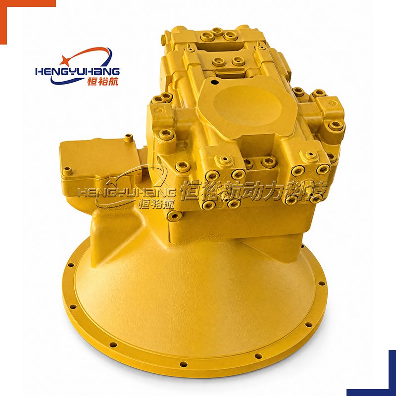
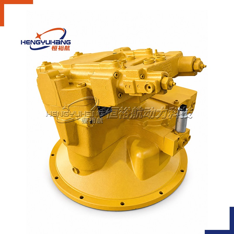
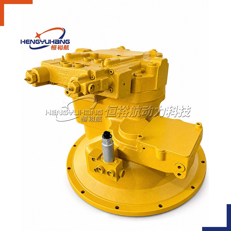
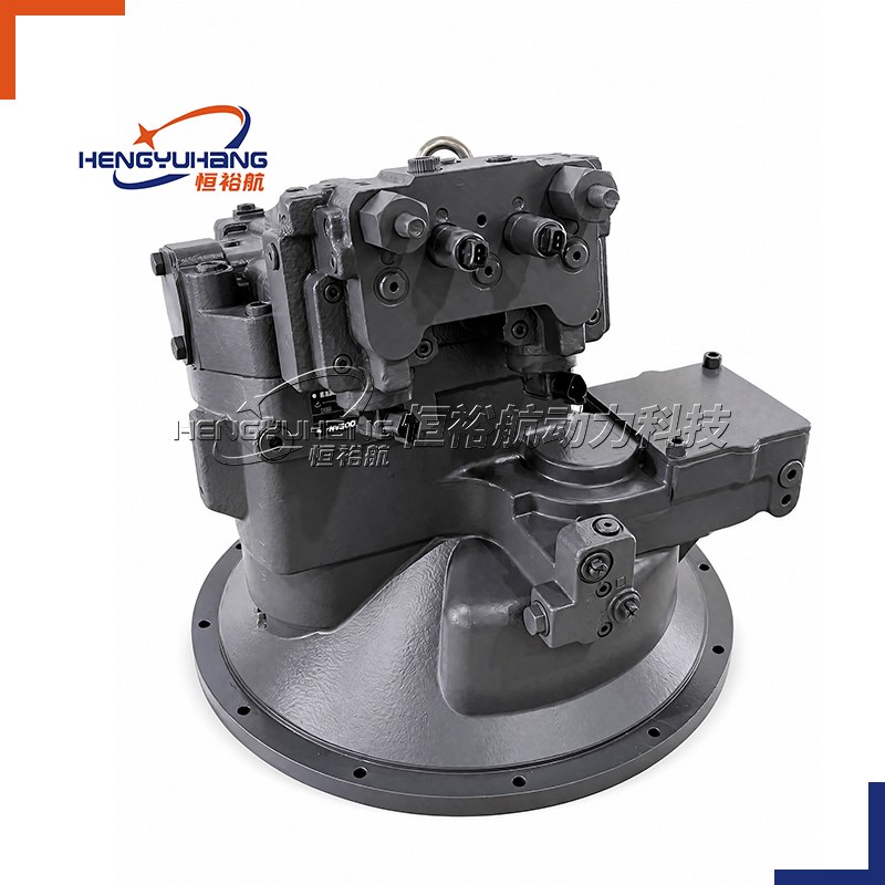
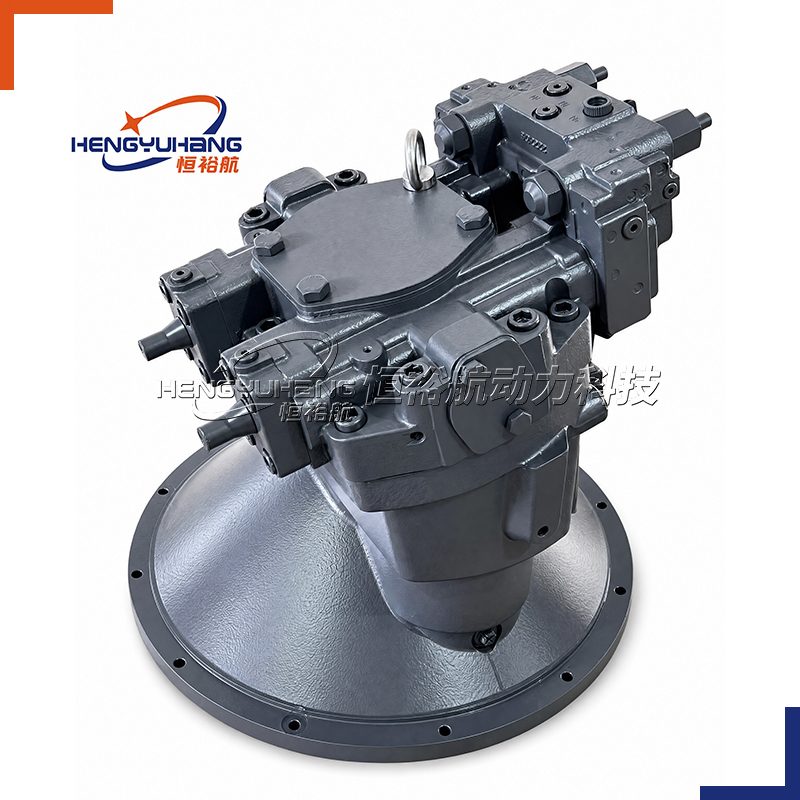
Piston pump
HENGYUHANG Axial Piston Variable Double Pump HYH8VO Series
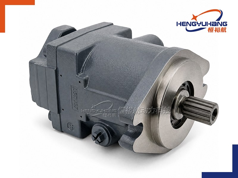
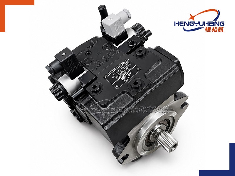
HENGYUHANG HYH8VO Series is a heavy-duty bent-axis axial tapered-piston variable double pump engineered for open-circuit hydrostatic drives, featuring two independent rotary groups in parallel construction, direct SAE J617 diesel engine flywheel housing mounting, a unified central suction port, integrated auxiliary charge/pilot pump, and seamless 1:1 drop-in interchangeability with Bosch Rexroth A8VO Series 61, 63, and 72 excavating pumps.
| Applications
Engineered primarily as the primary dual main hydraulic pump for crawler excavators (12-tonne to 55-tonne class), wheeled excavators, mobile and crawler cranes, rotary drilling rigs, hydraulic piling rigs, logging machinery, and heavy open-circuit mobile equipment requiring independent dual-flow high-pressure supply with high power-to-weight ratio and direct engine flywheel direct-drive mounting.
| Key Technical Specifications
Product Model: HYH8VO Series (Dual Pump Sizes: 2×54.8, 2×80.0, 2×107.0, 2×140.0, 2×200.0, 2×224.6 cm³/rev)
Brand Replacement: Bosch Rexroth A8VO Series 61, 63, and 72 (Sizes 55, 80, 107, 140, 200, 225), OEM or as requested.
Displacement: 2×54.8 / 2×80.0 / 2×107.0 / 2×140.0 / 2×200.0 / 2×224.6 cm³/rev (total combined output up to 2×460 L/min)
Rotation Direction: Clockwise (R), viewed facing input drive shaft
Speed Range: Rated speed at full displacement n max1 / n nom 1,950–2,500 rpm (n max up to 2,250–3,000 rpm at reduced swivel or boosted inlet; n min = 500 rpm)
Peak Pressure: Sizes 55–200: pN = 350 bar nominal / p max = 400 bar peak; Size 225: p nom = 380 bar nominal / p max = 420 bar peak
- Description
- Tecspecs
- Brand & Reference
- Download HENGYUHANG Axial Piston Variable Double Pump HYH8VO PDF
- Send an Inquiry
| Overview of HENGYUHANG HYH8VO Series Hydraulic Pumps
The HENGYUHANG HYH8VO Series is an ultra-heavy-duty bent-axis axial tapered-piston variable double pump specifically developed as the definitive main hydraulic power unit for mobile excavator and earthmoving hydrostatic transmission systems in open circuits. Featuring a compact parallel construction with two tapered-piston rotary groups driven synchronously through an internal distributor gear transmission (i=1.0), this series serves as an exact 1:1 functional, dimensional, and mechanical drop-in replacement for the entire Bosch Rexroth A8VO product family, including Series 61 and 63 (Sizes 55, 80, 107, 140, 200) and Series 72 (Size 225).
Operating fluid flow across both independent circuits is directly proportional to engine input speed and pump displacement, delivering smooth, stepless variation from full rated flow (qVmax) down to zero output (qVmin = 0). Designed specifically for direct bellhousing flange mounting onto diesel engine flywheel cases in accordance with SAE J617 standards (Housing Nos. 1, 3, and 4), the HYH8VO eliminates external pump drive gearboxes, intermediate cardan shafts, and cumbersome alignment procedures. A single enlarged common suction port S located at the rear feeds both primary rotary groups as well as an integrated auxiliary gear pump simultaneously. Equipped with individual cross-sensing hyperbolic power controllers (LA1 / LA0), load-sensing flow regulation, hydraulic stroke limiters, an integrated auxiliary charge/pilot pump with pressure-relief and reducing valves, and rear power take-off (PTO) flanges for mounting tertiary gear or piston pumps, the HYH8VO delivers unmatched power density, rugged reliability, and optimized diesel fuel efficiency under the harshest excavator digging and lifting duty cycles.
| Dimension of HENGYUHANG HYH8VO Series Hydraulic Pumps
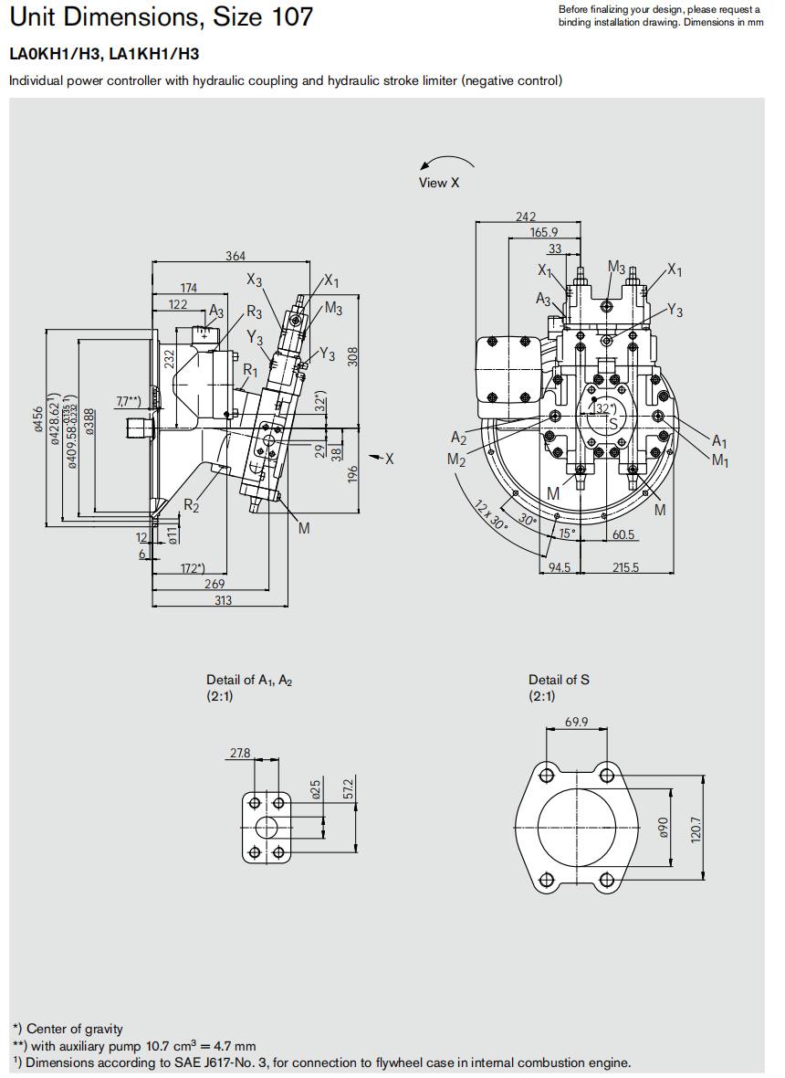
| Mechanical Installation Interface Specifications
| Frame Size (HYH8VO) | Flywheel Bellhousing Flange (SAE J617) | Input Drive Shaft Spline (DIN 5480) |
|---|---|---|
| HYH8VO55 | SAE J617 No. 4 (Ø361.95 mm pilot, 12×M10) | W40×2×30×18×9g (DIN 5480) |
| HYH8VO80 | SAE J617 No. 3 (Ø409.58 mm pilot, 12×M10) | W40×2×30×18×9g (DIN 5480) |
| HYH8VO107 | SAE J617 No. 3 (Ø409.58 mm pilot, 12×M10) | W45×2×30×21×9g (DIN 5480) |
| HYH8VO140 | SAE J617 No. 3 (Ø409.58 mm pilot, 12×M10) | W50×2×30×24×9g (DIN 5480) |
| HYH8VO200 | SAE J617 No. 1 (Ø511.18 mm pilot, 12×M10) | W50×2×30×24×9g (DIN 5480) |
| HYH8VO225 | SAE J617 No. 1 (Ø511.18 mm pilot, 12×M10) | W50×2×24×9g (DIN 5480) |
| Frame Size (HYH8VO) | Working Ports A1 and A2 (SAE J518 High-Pressure 6000 psi) | Common Suction Port S (SAE J518 Standard 3000 psi) | Auxiliary Pump Port A3 (DIN 3852-1) | Air Bleed & Drain Ports R1, R2, R3 (DIN 3852-1) | Control & Pilot Ports (DIN 3852-1) | Rear Power Take-Off (PTO) Flange |
|---|---|---|---|---|---|---|
| HYH8VO55 | 3/4 in (M10×1.5, 17 deep; 400 bar, Code 05) | 3 in (M16×2, 21 deep; 10 bar) | M18×1.5 (12 deep; 140 Nm) | R1, R2, R3: M14×1.5 (12 deep; 80 Nm) | M: M12×1.5; X1, X3, Y3: M14×1.5 | SAE A (82-2, 9T); SAE B (101-2, 13T/15T) |
| HYH8VO80 | 1 in (M12×1.75, 17 deep; 400 bar, Code 05) | 3 in (M16×2, 21 deep; 10 bar) | M18×1.5 (12 deep; 140 Nm) | R1, R2, R3: M14×1.5 (12 deep; 80 Nm) | M: M12×1.5; X1, X3, X4, Y3: M14×1.5 | SAE A, B, C (127-2, 14T) |
| HYH8VO107 | 1 in (M12×1.75, 17 deep; 400 bar, Code 05) | 3 1/2 in (M16×2, 21 deep; 10 bar) | M18×1.5 (12 deep; 140 Nm) | R1, R2, R3: M14×1.5 (12 deep; 80 Nm) | M: M12×1.5; M1, M2: M14×1.5; X1, X3, X4, Y3: M14×1.5 | SAE A, B, C (127-2, 14T) |
| HYH8VO140 | 1 in (M12×1.75, 17 deep; 400 bar, Code 05) | 4 in (M16×2, 21 deep; 10 bar) | M18×1.5 (12 deep; 140 Nm) | R1, R2, R3: M18×1.5 (12 deep; 140 Nm) | M: M12×1.5; X1, X3, X4, Y3: M14×1.5 | SAE A, B, C, D (152-4, 13T 8/16DP) |
| HYH8VO200 | 1 1/4 in (M12×1.75, 19 deep; 400 bar, Code 05) | 5 in (M16×2, 23 deep; 10 bar) | M18×1.5 (12 deep; 140 Nm) | R1, R2, R3: M22×1.5 (12 deep; 210 Nm); R4: M18×1.5 | M: M12×1.5; X1, X3, X4, Y3: M14×1.5 | SAE A, B, C, D (152-4, 13T 8/16DP) |
| HYH8VO225 | 1 1/4 in (M12×1.75, 19 deep; 420 bar, Code 05) | 5 in (M16×2, 23 deep; 1.5 bar) | M18×1.5 (12 deep; 40 bar) | R1, R2, R3: M22×1.5 (12 deep; 1.5 bar); R4: 3/4-16 UNF-2B | M: M12×1.5; M1, M2: M14×1.5; X1, X3, Y3: M14×1.5 | Rear PTO Hub up to 800 Nm |
| Interface Engineering Notes
Port Execution Code 05: Standard excavator port arrangement featuring two lateral opposite high-pressure service ports (A1 and A2) with metric DIN 13 fastening threads, and one common suction port S positioned at the rear.
Direct Flywheel Case Coupling: Bellhousing adapter pilot conforms to SAE J617 standards with hardened DIN 5480 female spline hubs or drive flanges matching standard diesel flywheel elastic couplings (e.g. Centa, Bowex).
Integrated Auxiliary Pump (Port A3): Built-in pilot gear pump feeds pilot joystick valves, brake release circuits, or cooling circuits directly via port A3 with factory-set pressure relief and reducing valves.
Dual Air Bleed Ports (R1, R3) and Drain (R2): Facilitate air purging and proper case drainage regardless of engine inclination.
| Pump Installation Specifications
| Complete Ordering Code Structure
HYH8V−O−[Size]−[Control]/[Series] R−[Seal][Gear Ratio][Flange][Shaft][Ports][Aux Pump][PTO][Valves]
| Position | Code Segment | Available Designations & Options | Technical Description & Functional Purpose |
|---|---|---|---|
| 01 | Axial Piston Unit | HYH8V / A8V | Bent-axis design, variable double pump in parallel construction |
| 02 | Operating Mode | O | Double pump for open circuits |
| 03 | Geometric Frame Size | 55, 80, 107, 140, 200, 225 | Nominal displacement per rotary group in cm³/rev |
| 04 | Control Devices | LA0H1 / LA0H2 LA0K / LA0KS / LA0KH1 / LA0KH2 LA1H1 / LA1H2 LA1K / LA1KS / LA1KH1 / LA1KH2 EP | LA0H1 / LA0H2: Individual power controller without override, hydraulic stroke limiter (positive control) LA0K / LA0KS / LA0KH1 / LA0KH2: Power controller with hydraulic power coupling, load sensing, or hydraulic stroke limiters LA1H1 / LA1H2: Individual power controller with pilot pressure override, positive stroke limiter LA1K / LA1KS / LA1KH1 / LA1KH2: Power controller with pilot pressure override, power coupling, load sensing, and stroke limiters EP: Electric proportional control with proportional solenoid (24V DC DEUTSCH connector) |
| 05 | Series | 61, 63, 72 | Series 6, Index 1 or 3 (Sizes 55–200); Series 7, Index 2 (Size 225) |
| 06 | Direction of Rotation | R | Clockwise (R), viewed facing drive shaft |
| 07 | Sealing Material | N, V | N: NBR nitrile rubber with FKM shaft seal ring; V: Full FKM fluorocarbon rubber seals |
| 08 | Transmission Ratio | 1 | Ratio i = ndrive / nrotary groups = 1.0 |
| 09 | Mounting Flange | G1, G2, G3, G4 | Flywheel case mount according to SAE J617: G1 (SAE 1), G2 (SAE 2), G3 (SAE 3), G4 (SAE 4) |
| 10 | Drive Shaft Spline | Z / A2 | Involute splined shaft according to DIN 5480 (W40 to W50) |
| 11 | Service Line Ports | 05 / 5 | Lateral opposite high-pressure ports A1 and A2, common rear suction port S (SAE J518, metric DIN 13 threads) |
| 12 | Auxiliary Pump | K00, K..., F00, F... | K00: Without auxiliary pump, without PTO; K..: With PTO only F00: With integrated auxiliary pump, without PTO; F..: With auxiliary pump and PTO |
| 13 | Power Take-Off (PTO) | 01, 02, 04, 07, 17, 86 | 01: SAE A (5/8" 9T); 02: SAE B (7/8" 13T); 04: SAE B-B (1" 15T) 07: SAE C (1 1/4" 14T); 17: SAE D (1 3/4" 13T); 86: SAE D (1 1/4" 14T) |
| 14 | Auxiliary Valve Block | 0, 1, 4 / A, C | 0: Without valves; 1 / A: With pressure-relief valve; 4 / C: With pressure-relief and reducing valve (U = 24 V) |
| Reading Your Replacement Code
| Rexroth OEM Model Code | HENGYUHANG Drop-In Code | Dual Displacement | Nominal/Peak Pressure | Controller Execution | Bellhousing & Auxiliary Configuration |
|---|---|---|---|---|---|
| A8VO55LA0KH1/61R-NZG405F001 | HYH8VO55LA0KH1/61R-NZG405F001 | 2×54.8 cm³/rev | 350 / 400 bar | Power + Coupling + Neg Limiter | SAE J617 No. 4, Aux Pump + Relief Valve |
| A8VO80LA1KH1/63R-NZG305F021 | HYH8VO80LA1KH1/63R-NZG305F021 | 2×80.0 cm³/rev | 350 / 400 bar | Power Override + Neg Limiter | SAE J617 No. 3, Aux Pump + SAE B PTO |
| A8VO107LA1KS/63R-NZG305F041 | HYH8VO107LA1KS/63R-NZG305F041 | 2×107.0 cm³/rev | 350 / 400 bar | Power Override + Load Sensing | SAE J617 No. 3, Aux Pump + SAE B-B PTO |
| A8VO140LA1KH2/63R-NZG305F074 | HYH8VO140LA1KH2/63R-NZG305F074 | 2×140.0 cm³/rev | 350 / 400 bar | Power Override + Pos Limiter | SAE J617 No. 3, Aux Pump + Relief/Red Valve + SAE C |
| A8VO200LA1KH1/63R-NZG105F174 | HYH8VO200LA1KH1/63R-NZG105F174 | 2×200.0 cm³/rev | 350 / 400 bar | Power Override + Neg Limiter | SAE J617 No. 1, Aux Pump + Relief/Red Valve + SAE D |
| A8VO2250/72MR-N1G1A25-F0000C | HYH8VO225LA1KH1/72R-N1G1A25-F0000C | 2×224.6 cm³/rev | 380 / 420 bar | Series 72 Power Override (LA1KH1) | SAE J617 No. 1, Aux Pump + Relief/Red Valve |
Technical Specifications of HENGYUHANG HYH8VO Series (Tandem Bent-Axis, Sizes 55–225)
4.1 Dual Rotary Group Performance Matrix (Data at pₐᵦₛ=1.0 bar at port S, mineral fluid ρ=0.88 kg/L)
| Performance Parameter | Unit | HYH8VO55 | HYH8VO80 | HYH8VO107 | HYH8VO140 | HYH8VO200 | HYH8VO225 |
|---|---|---|---|---|---|---|---|
| Max Displacement per Rotary Group (Vgₘₐₓ) | cm³/rev | 54.8 | 80.0 | 107.0 | 140.0 | 200.0 | 224.6 |
| Combined Maximum Displacement (2×Vgₘₐₓ) | cm³/rev | 109.6 | 160.0 | 214.0 | 280.0 | 400.0 | 449.2 |
| Minimum Displacement (Vg min) | cm³/rev | 0 | 0 | 0 | 0 | 0 | 0 |
| Transmission Gear Ratio (i = n_input/n_rotary groups) | — | 1.0 | 1.0 | 1.0 | 1.0 | 1.0 | 1.0 |
| Max Input Speed at Full Displacement (n_max1/nₙₒₘ) | rpm | 2,500 | 2,240 | 2,150 | 2,100 | 1,950 | 2,050 |
| Limiting Input Speed (nₘₐₓ at reduced swivel angle) | rpm | 3,000 | 2,750 | 2,450 | 2,450 | 2,250 | 2,300 |
| Minimum Operating Speed (nₘᵢₙ) | rpm | 500 | 500 | 500 | 500 | 500 | 500 |
| Maximum Delivery Flow (qV at n_max1 and Vgₘₐₓ) | L/min | 2×137 | 2×179 | 2×230 | 2×294 | 2×390 | 2×460 |
| Maximum Continuous Drive Power (P_max at Δp) | kW | 160 (350 bar) | 209 (350 bar) | 268 (350 bar) | 294 (350 bar) | 325 (350 bar) | 384 (250 bar) |
| Maximum Input Torque (T_max at Δp) | Nm | 611 (350 bar) | 891 (350 bar) | 1,192 (350 bar) | 1,337 (350 bar) | 1,592 (350 bar) | 1,788 (250 bar) |
| Rotary Stiffness per Group (c_TW from Vgₘₐₓ to 0.5Vg) | kNm/rad | 11.2 | 18.0 | 25.6 | 41.4 | 39.5 | 73.0 |
| Rotary Group Moment of Inertia with PTO (J_TW) | kg·m² | 0.0161 | 0.0209 | 0.0345 | 0.0581 | 0.0849 | 0.0879 |
| Max Permissible Angular Acceleration (α) | rad/s² | 25,800 | 21,800 | 17,100 | 7,500 | 11,000 | 10,000 |
| Dry Weight without PTO / Aux Pump (Approx.) | kg | 82 | 90 | 116 | 146 | 180 | 194 |
| Integrated Aux Pump Effective Displacement (Vg_eff) | cm³/rev | 9.7 | 9.7 | 11.0 (13.7) | 12.7 | 13.6 (23.6) | 13.6 (23.6) |
| Max Permissible Torque at Power Take-Off (PTO) | Nm | 250 | 350 | 380 | 450 | 650 | 800 |
4.2 Operating Pressure Boundaries
| Pressure Characteristic | Permissible Value (Sizes 55–200) | Permissible Value (Size 225 Series 72) | Operational Definition & Safety Limits |
|---|---|---|---|
| Nominal Operating Pressure (p_N/pₙₒₘ) | 350 bar (5,100 psi) | 380 bar (5,500 psi) | Maximum continuous design fatigue pressure according to DIN/ISO standards |
| Maximum Peak Pressure (pₘₐₓ) | 400 bar (5,800 psi) | 420 bar (6,100 psi) | Maximum transient shock pressure (t<1.0 s, total accumulated ≤300 h) |
| Minimum Pressure on Service Ports A1/A2 | ≥10 bar (145 psi) absolute | ≥12 bar (174 psi) absolute | Required on high-pressure side to prevent tapered piston unseating |
| Rate of Pressure Change (RAₘₐₓ) | 16,000 bar/s | 16,000 bar/s | Maximum permissible rate of pressure build-up and pressure drop across duty |
| Suction Port Minimum Pressure (p_S min at Port S) | ≥0.8 bar (11.6 psi) absolute | ≥0.8 bar (11.6 psi) absolute | Minimum inlet suction pressure to prevent cavitation at rated speed |
| Case Drain Permissible Pressure (p_L/p_case) | ≤2.0 bar (29 psi) absolute | ≤1.5 bar (21.7 psi) absolute | Continuous case pressure measured at ports R1/R2/R3; peak ≤3.0 bar |
| Auxiliary Pump Working Pressure (Port A3) | ≤40 bar (580 psi) | ≤40 bar (580 psi) | Continuous pilot pressure supplied to pilot joysticks and control blocks |
4.3 Hydraulic Fluid & Temperature Operational Limits
| Fluid Characteristic | Permissible Value | Operational Note |
|---|---|---|
| Recommended Fluid Media | Mineral oil (HLP to DIN 51524) | High-performance petroleum-based hydraulic fluid with anti-wear additives |
| Optimum Operating Viscosity (νₒₚₜ) | 16 to 36 mm²/s | Optimum balance of volumetric efficiency, response time, and bearing life |
| Continuous Operating Viscosity | 10 to 400 mm²/s | Full operational envelope with continuous temperature monitoring |
| Minimum Viscosity (νₘᵢₙ) | 5 mm²/s | Short-term limit (t≤3 min) at t_max=+115 ∘C and reduced load |
| Maximum Viscosity at Cold Start (νₘₐₓ) | 1,600 mm²/s | Permissible at cold start (p≤30 bar, n≤1,000 rpm, t_min=−40 ∘C, no-load ≤15 min) |
| Permissible Fluid Temperature Range | −40 ∘C to +115 ∘C (−40 ∘F to +239 ∘F) | Case drain temperature must never exceed +115 ∘C at any point |
| Fluid Cleanliness Class | ISO 4406 Class 20/18/15 | At elevated temperatures (>90 ∘C), maintain Class 19/17/14 minimum |
Product Advantages
Heavy-Duty Bent-Axis Tapered-Piston Rotary Architecture
Bent-axis spherical cylinder design with one-piece tapered pistons and piston rings delivers superior mechanical-hydraulic efficiency (>92%), high starting torque, and exceptional resistance to particle contamination.
Direct Flywheel Housing Mounting (SAE J617)
Bolted directly onto the diesel engine bellhousing (SAE 1, 3, or 4), eliminating intermediate transfer gearboxes, drive shafts, and flexible couplings for maximum powertrain compactness.
Integrated Auxiliary Pilot Pump
Built-in auxiliary gear pump driven internally off the distributor shaft supplies continuous 40 bar pilot oil for excavator pilot joysticks, brake valves, and control manifolds, eliminating separate engine-driven gear pumps.
Unified Central Suction Port S
A single, large SAE suction flange feeds both primary rotary groups and the auxiliary pump simultaneously, dramatically reducing tank suction piping complexity.
Independent Cross-Sensing Power Management
Dual LA1/LA0 hyperbolic power regulators limit total combined engine torque absorption across both digging circuits, preventing diesel engine overload and stalling during heavy simultaneous boom/arm/bucket operations.
Full Auxiliary Power Take-Off (PTO)
Rear through-drive mounting pads (SAE A, B, C, D) transmit up to 800 Nm auxiliary torque for tertiary swing circuit pumps, cooling fan pumps, or travel boost units.
| Interchangeability & Cross Reference
6.1 Direct Replacement Matrix: Bosch Rexroth A8VO to HENGYUHANG HYH8VO
| OEM Model Code | Displacement Band | Nominal/Peak Pressure | Bellhousing Flange | Service Ports A1/A2 & S | HENGYUHANG 1:1 Replacement |
| A8VO55.../61 | 2×54.8 cm³/rev | 350 / 400 bar | SAE J617 No. 4 (G4) | SAE 3/4" High Pressure / SAE 3" Suction | HYH8VO55 |
| A8VO80.../63 | 2×80.0 cm³/rev | 350 / 400 bar | SAE J617 No. 3 (G3) | SAE 1" High Pressure / SAE 3" Suction | HYH8VO80 |
| A8VO107.../63 | 2×107.0 cm³/rev | 350 / 400 bar | SAE J617 No. 3 (G3) | SAE 1" High Pressure / SAE 3 1/2" Suction | HYH8VO107 |
| A8VO140.../63 | 2×140.0 cm³/rev | 350 / 400 bar | SAE J617 No. 3 (G3) | SAE 1" High Pressure / SAE 4" Suction | HYH8VO140 |
| A8VO200.../63 | 2×200.0 cm³/rev | 350 / 400 bar | SAE J617 No. 1 (G1) | SAE 1 1/4" High Pressure / SAE 5" Suction | HYH8VO200 |
| A8VO225.../72 | 2×224.6 cm³/rev | 380 / 420 bar | SAE J617 No. 1 (G1) | SAE 1 1/4" High Pressure / SAE 5" Suction | HYH8VO225 |
6.2 Modular Controller Functionality Mapping
| Controller Code | Functional Designation | Operational Characteristic & Machine Control Role |
| LA0H1 / LA0H2 | Individual Power Controller + Positive Stroke Limiter | Regulates displacement hyperbolic curve; external pilot pressure sets maximum flow limitation |
| LA0K / LA0KS | Power Controller + Hydraulic Power Coupling + LS | Hydraulically couples both pump powers for total summation; incorporates load-sensing flow regulation |
| LA0KH1 / LA0KH2 | Power Controller + Coupling + Hydraulic Stroke Limiter | Summation power regulation with hydraulic minimum or maximum displacement stroke limitation |
| LA1KH1 | Power Controller with Pilot Override + Coupling + Negative Limiter | Pilot pressure signal (port X3) overrides base power setting; negative control strokes back pump with increasing pilot pressure |
| LA1KH2 | Power Controller with Pilot Override + Coupling + Positive Limiter | Pilot pressure signal (port X3) overrides base power setting; positive control strokes up pump with increasing pilot pressure |
| EP | Electrohydraulic Proportional Control | Proportional electrical solenoid (24V DC) adjusts pump swashplate angle directly via digital machine controller |
| Brand Replacement
Bosch Rexroth (Primary 1:1 direct interchangeability for A8VO Series 61, 63, and 72 bent-axis variable double pumps)
Kawasaki (K3V / K5V Series excavator dual pumps) and Komatsu (HPV Series) retrofits engineered with customized engine adapter plates
Caterpillar, Kobelco, Hitachi, and SANY excavator dual main pump replacements with 100% drop-in mechanical mounting
| Applications
Hydraulic Crawler Excavators (12T to 55T): Primary dual main hydraulic pump directly coupled to diesel engine flywheel, powering boom, stick, bucket, and dual independent travel tracks.
Wheeled Excavators & Material Handlers: High-speed, high-pressure dual circuits for simultaneous digging, slewing, and outrigger positioning.
Hydraulic Rotary Drilling & Piling Rigs: Dual high-pressure supplies for high-torque rotary drive heads and crowd feed cylinders.
Timber Harvesters & Forestry Loaders: Smooth multi-actuator coordination with independent power management preventing engine stall.
Mobile Harbor Cranes & Demolition Machines: Dedicated circuits for high-pressure demolition shear crushing and rapid arm articulation.
| Packaging & Shipping
| Packaging Layer | Specification & Protection Material | Safety Standard |
| Inner Protection | Corrosion-inhibiting VCI plastic wrap, desiccants, and heavy-duty port thread plugs | Prevents moisture, atmospheric corrosion, and debris contamination |
| Shock Cushioning | Custom-molded high-density expanded polyethylene (EPE) foam enclosure | Absorbs severe multi-axis transit impacts and protects shaft extensions |
| Outer Enclosure | ISPM-15 export-certified solid fumigation-free engineered wooden crate | Structural reinforcement for global ocean, air, and multimodal handling |
| Logistics Options | Express Courier (DHL, FedEx, UPS), Air Freight, LCL/FCL Ocean Cargo, DDP door-to-door | Dispatch in 48–72 hours for standard configurations; tailored tracking provided |
| Why Choose Hengyuhang?
Direct Factory Precision Manufacturing & CNC Excellence: State-of-the-art multi-axis CNC machining centers, precision spherical grinding equipment, and sub-micron gear and bearing fitment (Ra < 0.2 μm) guarantee superior rotary group alignment and low internal leakage.
100% Full-Cycle Multi-Parameter Factory Inspection: Every HYH8VO double pump undergoes automated dual-circuit test-bench trials verifying volumetric efficiency (> 94%), continuous and peak pressure hold at 350/400/420 bar, auxiliary pump output, response hysteresis, and vibration/noise spectra prior to dispatch.
Seamless 1:1 OEM Drop-In Interchangeability: Engineered to match European DIN, ISO, and SAE standards down to the millimeter, allowing immediate replacement of Bosch Rexroth A8VO Series 61, 63, and 72 units with zero pipe rework or bracket modification.
Flexible Engineering Customization & Rapid Prototyping: In-house hydraulic engineering team provides tailored control-valve calibrations, special shaft profiles, auxiliary flushing ports, and rapid prototype turnarounds with minimal MOQ requirements.
Robust Supply Chain, Extensive Inventory & Fast Global Dispatch: Continuous inventory of finished cast bodies, bearing kits, rotary groups, and modular controllers enables standardized orders to ship globally within 48 to 72 hours.
12-Month Comprehensive Warranty & Lifetime Technical Support: All units are backed by an unconditional 12-month factory warranty, 24-hour drawing verification service, and lifetime engineering consultation from certified fluid power specialists.
HENGYUHANG Axial Piston Variable Double Pump HYH8VO Series 61 / 63 / 72 (Variable Bent-Axis Open-Circuit Hydraulic Double Pump, 2×54.80~2×224.60 cm³/rev) is a high-pressure, heavy-duty axial piston variable double pump incorporating two axial tapered piston rotary groups arranged in parallel bent-axis architecture within a single monoblock housing for demanding open-circuit hydrostatic drives in mobile construction machinery, heavy hydraulic mining excavators, and drilling rigs. Manufactured by Quanzhou Hengyuhang Power Technology Co., Ltd. as an engineered, direct-fit replacement line designed to match the benchmark performance, mounting dimensions, pressure ratings, and hydraulic characteristics of the Rexroth A8VO Series 61, Series 63, and Series 72 (RE 93010 / RE 93013), the HYH8VO Series delivers superior power density, proven bent-axis mechanical durability, and smooth, stepless displacement regulation from zero to maximum flow. Fluid delivery flow is directly proportional to drive speed and displacement angle. Across its 6 primary frame sizes—HYH8VO-55, HYH8VO-80, HYH8VO-107, HYH8VO-140, HYH8VO-200, and HYH8VO-225—the series operates at a continuous nominal working pressure of 350 bar (5100 psi / 35 MPa) and a maximum peak pressure of 400 bar (5800 psi / 40 MPa) on Sizes 55~200 (Series 61/63), and up to 380 bar nominal / 420 bar peak pressure on Size 225 (Series 72). The pump mounts directly onto the diesel engine flywheel housing conforming to standard SAE J617 specifications (Flywheel sizes No. 4, No. 3, and No. 1), featuring a single shared suction port S that feeds both main rotary groups and an integrated auxiliary pilot pump. With a wide range of modular control devices including individual power controllers (LA0/LA1), hydraulic stroke limiters (H1/H2/H3), hydraulic power coupling (K), load-sensing flow matching (S/KS), electric proportional overrides (EP2/LE2), and heavy-duty rear Power Take-Off (PTO) mountings (SAE A, B, C, D) capable of transferring up to 800 Nm of auxiliary torque, the HYH8VO Series provides a proven, drop-in replacement solution for modern excavator hydraulic systems.
| Applications
The HYH8VO Series variable bent-axis double pump is engineered specifically for heavy-duty, twin-circuit open-circuit work hydraulics in high-tonnage mobile earthmoving machinery, severe mining excavators, and rotary drilling platforms requiring direct flywheel engine coupling and compact dual-flow delivery:
Heavy Hydraulic Mining & Crawler Excavators: Main implement and travel hydraulic double pump for 20-ton to 90-ton crawler excavators, supplying independent 350~380 bar power streams for boom lift, stick crowd, bucket curl, and simultaneous high-torque crawler travel.
Rotary Drilling Rigs & Foundation Piling Rigs: Direct engine flywheel-mounted dual-pump power generation driving rotary powerhead continuous high-torque drilling on circuit 1 while simultaneously powering main mast winches, crowd cylinders, and auxiliary casing oscillators on circuit 2.
Wheeled & Material Handling Excavators: Powers heavy scrap handling grabs, sorting grapples, telescoping material handler arms, and hydrostatic all-wheel travel circuits under continuous cyclic load reversals.
Demolition & Forestry Harvester Equipment: Supplies simultaneous high-flow hydraulic circuits for tree felling heads, delimbing feed rollers, high-impact hydraulic breakers, and concrete crushing shears.
Mobile Crushing & Screening Plants: Compact direct-mount double pump driving heavy eccentric crusher jaw motors, feeder conveyors, and vibratory screening decks from an engine power take-off skid.
Multi-Circuit Auxiliary Power Packs (Splitter Gearbox Elimination): Directly couples two high-pressure bent-axis rotary groups to the engine flywheel without splitter gearboxes, utilizing standard rear PTO mountings (SAE A, B, C, D) to drive auxiliary pilot, cooling fan, or steering gear pumps.
| Key Specifications Overview
| Parameter | Hengyuhang HYH8VO Series Specification (OEM Benchmark Standard) |
|---|---|
| Pump Classification | Axial Piston Variable Double Pump in Bent-Axis Design for Open Circuits (HYH8VO Series 61 / 63 / 72) |
| OEM Interchange Reference | Direct 1:1 physical, dimensional, and hydraulic drop-in replacement for Rexroth A8VO Series 61/63 (RE 93010) and Series 72 (RE 93013) |
| Displacement Size Range | 6 Heavy-Duty Frame Sizes: 2×54.8, 2×80.0, 2×107.0, 2×140.0, 2×200.0, and 2×224.6 cm³/rev per rotary group |
| Rotary Group Architecture | Dual parallel axial tapered piston rotary groups of bent-axis design with heavy-duty spherical cylinder control plates |
| Nominal Continuous Pressure (pN / pnom) | Sizes 55~200: 350 bar (5100 psi / 35 MPa); Size 225 (Series 72): 380 bar (5500 psi / 38 MPa) continuous working pressure at ports A1 and A2 |
| Maximum Peak Operating Pressure (pmax) | Sizes 55~200: 400 bar (5800 psi / 40 MPa); Size 225: 420 bar (6100 psi / 42 MPa) peak pressure (single period < 1 s / < 10 s; total 300 h) |
| Minimum Pressure at High-Pressure Port | Size 225: 25 bar absolute holding pressure required at ports A1 and A2 to prevent damage during high-speed deceleration |
| Rate of Pressure Change (RA max) | Size 225: 9000 bar/s (130,530 psi/s) maximum permissible rate of pressure build-up and reduction across entire operating range |
| Nominal Rotational Speed Range (at Vg max, pabs = 1 bar) | Nominal drive speeds from 1950 rpm (Size 200) up to 2500 rpm (Size 55); Maximum speed at reduced displacement up to 3000 rpm |
| Suction Pressure Range (Port S Inlet) | Minimum inlet pressure pS min ≥ 0.8 bar absolute at n_nom (higher speed requires boosted inlet pressure); Maximum pS max ≤ 1.5~2.0 bar absolute |
| Internal Case Drain System | Case drain chamber is internally connected to suction and gear chambers; external tank drain line is not required (Size 200/225 features port R4 flushing line) |
| Mounting Flange Standards | Conforming to SAE J617 diesel engine flywheel case mounting: SAE J617-No. 4 (Size 55); SAE J617-No. 3 (Sizes 80, 107, 140); SAE J617-No. 1 (Sizes 200, 225) |
| Drive Shaft Configurations | Splined shaft DIN 5480 Code Z: W40×2 (Sizes 55, 80), W45×2 (Size 107), W50×2 (Sizes 140, 200, 225) driven via flexible engine coupling |
| Working Fluid Ports (Dual Outlets A1, A2) | SAE J518 Code 62 High Pressure: 3/4 in (Size 55); 1 in (Sizes 80, 107, 140); 1 1/4 in (Sizes 200, 225), located on opposite lateral sides |
| Suction Fluid Port (Shared Single Inlet S) | SAE J518 Code 61 Standard Pressure: 3 in (Sizes 55, 80); 3 1/2 in (Size 107); 4 in (Size 140); 5 in (Sizes 200, 225), located centrally at rear |
| Integrated Auxiliary Pump (Port A3) | Built-in auxiliary gear pump (Vg = 8.6~19 cm³) with integrated 30 bar pressure-relief valve (max 40 bar) and optional 24V pressure-reducing valve |
| Sealing Material System | Code N: NBR (nitrile-caoutchouc) with premium FKM shaft seal ring (-40°C to +115°C permissible case fluid temperature) |
| Direction of Rotation | Clockwise rotation (Code R), viewed facing input drive shaft end (gear ratio i = 1.0 between input shaft and rotary groups) |
| Operating Viscosity Range | Optimum: νopt = 16 to 36 mm²/s; Permissible: νmin = 5 mm²/s (short-term at 115°C); Maximum cold start: νmax ≤ 1600 mm²/s |
| Fluid Cleanliness Standard | ISO 4406 Class 20/18/15 minimum (Class 19/17/14 recommended for high fluid temperatures from 90°C to 103°C) |
| Power Take-Off (PTO) Capability | Rear PTO mountings (SAE A, B, C, D) for driving auxiliary gear or piston pumps with torque transfer ratings from 250 Nm up to 800 Nm |
| Technical Performance Matrix Across Available Sizes
| ■ Variable Bent-Axis Double Pump Series (HYH8VO — 350~380 bar Nominal / 400~420 bar Peak Benchmark) | ||||||||||||
|---|---|---|---|---|---|---|---|---|---|---|---|---|
| Model Number (Hengyuhang Series) | Displacement per Group (cm³) | Drive Speed (rpm) | Total Delivery Flow @ nmax1 (L/min) | Nominal Pressure pN / pnom (bar) | Drive Power Pmax (kW) | Input Torque Tmax (Nm) | Rotary Stiffness cTW (kNm/rad) | Inertia JTW w/ PTO (kg·m²) | Angular Accel. α (rad/s²) | Unit Mass m approx. (kg) | ||
| Nominal nmax1 | Max nmax | Vg max to 0.5 | 0.5 to 0 (interp.) | |||||||||
| HYH8VO-55 | 54.80 (2×54.8) | 2500 | 3000 | 2 × 137 (274.0) | 350 (max 400) | 160.0 | 611.0 | 11.21 | 41.44 | 0.0161 | 25,800 | 82.0 |
| HYH8VO-80 | 80.00 (2×80.0) | 2240 | 2750 | 2 × 179 (358.0) | 350 (max 400) | 209.0 | 891.0 | 17.98 | 67.67 | 0.0209 | 21,800 | 90.0 |
| HYH8VO-107 | 107.00 (2×107.0) | 2150 | 2450 | 2 × 230 (460.0) | 350 (max 400) | 268.0 | 1192.0 | 25.56 | 89.38 | 0.0345 | 17,100 | 116.0 |
| HYH8VO-140 | 140.00 (2×140.0) | 2100 | 2450 | 2 × 294 (588.0) | 350 (max 400) | 294.0 | 1337.0 | 41.41 | 146.68 | 0.0581 | 7500 | 146.0 |
| HYH8VO-200 | 200.00 (2×200.0) | 1950 | 2250 | 2 × 390 (780.0) | 350 (max 400) | 325.0 | 1592.0 | 39.51 | 156.88 | 0.0849 | 11,000 | 180.0 |
| HYH8VO-225 | 224.60 (2×224.6) | 2050 | 2300 | 2 × 460 (920.0) | 380 (max 420) | 384.0 | 1788.0 | 73.00 | 318.68 | 0.0879 | 10,000 | 194.0 |
| Control Devices & Operating Regulating Instruments
| Control Code | Control Classification | Control Signal & Pilot Supply | Functional Operation & Machine Circuit Application |
|---|---|---|---|
| LA0 / LA0H1 / LA0H2 | Individual Power Controller (Without Override) | Internal working pressure sensing with measuring springs; port X1 stroke limiter | Controls displacement depending on operating pressure so that preset input power is not exceeded. Each rotary group operates independently with separate power settings up to 100% drive power. |
| LA0S / LA0KS | Individual Power Controller with Load-Sensing | Load-sensing differential pilot pressure at port X4 | Combines hyperbolic horsepower limiting with hydraulic load-sensing flow matching to ensure variable flow delivery proportional to control valve spool opening. |
| LA0K / LA0KH1 / LA0KH2 | Individual Power Controller with Power Coupling | Internal hydraulic cross-coupling spool between both rotary groups | Hydraulic power coupling dynamically balances power absorption between both circuits, preventing engine overload while allowing full single-circuit power utilization. |
| LA1 / LA1H1 / LA1H2 | Power Controller with Pilot Pressure Power Override | External pilot pressure signal applied to differential piston at port X3 | Enables continuous reduction or variation of the preset basic power curve via external hydraulic pilot pressure (negative power override) for engine load-limiting control. |
| LA1KH1 / LA1KH2 | Power Controller with Power Coupling & Stroke Limiter | Power coupling with pilot override at port X3 and stroke limiter at port X1 | Standard heavy excavator configuration: combines dynamic hydraulic power cross-coupling, external pilot power override, and stroke limitation (KH1 negative / KH2 positive control). |
| LA1S / LA1KS | Power Controller with Power Override & Load-Sensing | Pilot pressure override at port X3 and load-sensing signal at port X4 | Advanced multi-function excavator control combining engine anti-stall load limiting, hydraulic twin-circuit power summation, and load-sensing flow regulation. |
| EP2 | Electrical Proportional Displacement Control | Proportional electric current (24V DC solenoid, DEUTSCH connector) | Direct electrical proportional displacement control (positive control) for digital computerized mobile machine control architectures (Sizes 107 and 140). |
| Mounting Flange, Shaft and Port Specifications Across Sizes
| Mechanical Installation Interface (Mounting Flange & Drive Shaft) | ||
|---|---|---|
| Frame Size Model | Mounting Flange Standards (Engine Flywheel Housing) | Drive Shaft Options (Splined Standards DIN 5480) |
| HYH8VO-55 | Code G: Conforming to SAE J617-No. 4 (Flywheel case No. 4, fixing hole Ø11 mm) | Code Z: Splined shaft DIN 5480 W40×2×30×18×9g (driven via flexible coupling) |
| HYH8VO-80 | Code G: Conforming to SAE J617-No. 3 (Flywheel case No. 3, fixing hole Ø11 mm) | Code Z: Splined shaft DIN 5480 W40×2×30×18×9g (driven via flexible coupling) |
| HYH8VO-107 | Code G: Conforming to SAE J617-No. 3 (Flywheel case No. 3, fixing hole Ø11 mm) | Code Z: Splined shaft DIN 5480 W45×2×30×21×9g (driven via flexible coupling) |
| HYH8VO-140 | Code G: Conforming to SAE J617-No. 3 (Flywheel case No. 3, fixing hole Ø11 mm) | Code Z: Splined shaft DIN 5480 W50×2×30×24×9g (driven via flexible coupling) |
| HYH8VO-200 | Code N: Conforming to SAE J617-No. 1 (Flywheel case No. 1, fixing hole Ø11 mm) | Code Z: Splined shaft DIN 5480 W50×2×30×24×9g (driven via flexible coupling) |
| HYH8VO-225 | Code G1: Conforming to SAE J617-No. 1 (Flywheel case No. 1, fixing hole Ø11 mm) | Code A2: Splined shaft DIN 5480 W50×2×24×9g (driven via flexible coupling) |
| Fluid Port Configuration (Service, Suction, Auxiliary Pump, Bleed, Drain & Gauge Ports) | |||||
|---|---|---|---|---|---|
| Frame Size Model | Dual Working Ports A1, A2 (SAE J518) | Shared Suction Port S (SAE J518) | Auxiliary Pump Port A3 | Bleed & Drain Ports R1~R4 | Gauge & Pilot Ports |
| HYH8VO-55 | SAE J518 3/4 in (400 bar, M10×1.5; 17 deep) | SAE J518 3 in (M16×2; 21 deep) | DIN 3852 M18×1.5; 12 deep (40 bar) | R1, R3 bleed: M14×1.5; R2 drain: M14×1.5 | M: M12×1.5; M3: M14×1.5; X1, X3, Y3: M14×1.5 |
| HYH8VO-80 | SAE J518 1 in (400 bar, M12×1.75; 17 deep) | SAE J518 3 in (M16×2; 21 deep) | DIN 3852 M18×1.5; 12 deep (40 bar) | R1, R3 bleed: M14×1.5; R2 drain: M14×1.5 | M: M12×1.5; M1/M2: 9/16-18UNF; X1, X3, X4, Y3: M14×1.5 |
| HYH8VO-107 | SAE J518 1 in (400 bar, M12×1.75; 17 deep) | SAE J518 3 1/2 in (M16×2; 21 deep) | DIN 3852 M18×1.5; 12 deep (40 bar) | R1, R3 bleed: M14×1.5; R2 drain: M14×1.5 | M: M12×1.5; M1/M2: M14×1.5; X1, X3, X4, Y3: M14×1.5 |
| HYH8VO-140 | SAE J518 1 in (400 bar, M12×1.75; 17 deep) | SAE J518 4 in (M16×2; 21 deep) | DIN 3852 M18×1.5; 12 deep (40 bar) | R1, R3 bleed: M18×1.5; R2 drain: M18×1.5 | M: M12×1.5; M1/M2: 9/16-18UNF; X1, X3, X4, Y3: M14×1.5 |
| HYH8VO-200 | SAE J518 1 1/4 in (400 bar, M12×1.75; 19 deep) | SAE J518 5 in (M16×2; 23 deep) | DIN 3852 M18×1.5; 12 deep (40 bar) | R1, R3 bleed: M22×1.5; R4 flushing: M18×1.5 | M: M12×1.5; M1/M2: 9/16-18UNF; X1, X3, X4, Y3: M14×1.5 |
| HYH8VO-225 | SAE J518 1 1/4 in (420 bar, M12×1.75; 19 deep) | SAE J518 5 in (M16×2; 23 deep) | DIN 3852 M18×1.5; 12 deep (40 bar) | R1, R3 bleed: M22×1.5; R4 flushing: 3/4-16 UNF | M: M12×1.5; M1/M2: M14×1.5; X1, X3, Y3: M14×1.5 |
| Power Take-Off (PTO) & Auxiliary Pump Options
| PTO Option Code | Mounting Flange Standard | Internal Splined Coupling Hub | Applicable Pump Sizes & Maximum Torque Transfer |
|---|---|---|---|
| K00 / F00 | Without power take-off (PTO) | None (closed rear housing end) | K00: without auxiliary pump; F00: with integrated auxiliary pump (Sizes 55~225) |
| K01 / F01 | SAE J744 82-2 (SAE A 2-bolt) | ANSI B92.1a 5/8 in 9T 16/32DP | Mounting auxiliary gear pumps AZPF for pilot pressure or brake supply (Tmax = 250 Nm) |
| K02 / F02 | SAE J744 101-2 (SAE B 2-bolt) | ANSI B92.1a 7/8 in 13T 16/32DP | Mounting auxiliary gear pumps AZPN/AZPG or HYH10VO-28 for steering/cooling (Tmax = 350 Nm) |
| K04 / F04 | SAE J744 101-2 (SAE B 2-bolt) | ANSI B92.1a 1 in 15T 16/32DP | Mounting secondary HYH10VO-45 piston pumps for auxiliary implement functions (Tmax = 380 Nm) |
| K07 / F07 | SAE J744 127-2 (SAE C 2-bolt) | ANSI B92.1a 1 1/4 in 14T 12/24DP | Mounting secondary HYH10VO-60/71/100 or HYH11VO-60 piston pumps (Tmax = 450 Nm) |
| K86 / F86 | SAE J744 152-4 (SAE D 4-bolt) | ANSI B92.1a 1 1/4 in 14T 12/24DP | Mounting secondary heavy-duty piston pumps HYH11VO-75 on Sizes 140, 200, 225 (Tmax = 650 Nm) |
| K17 / F17 | SAE J744 152-4 (SAE D 4-bolt) | ANSI B92.1a 1 3/4 in 13T 8/16DP | Mounting secondary heavy-duty piston pumps HYH11VO-95/130 on Sizes 140, 200, 225 (Tmax = 800 Nm) |
| Direct Interchangeability and OEM Replacement Matrix (Rexroth A8VO Series 61 / 63 / 72)
| Hengyuhang Series Model | Rexroth OEM Reference Model (A8VO Series 61/63/72) | Interchangeability Verification Status |
|---|---|---|
| HYH8VO-55 | A8VO 55 LA1KH1 / 61R1-NZG05F001 | 100% Direct Physical, Dimensional & Hydraulic Drop-in Replacement |
| HYH8VO-80 | A8VO 80 LA1KH1 / 63R1-NZG05F001 | 100% Direct Physical, Dimensional & Hydraulic Drop-in Replacement |
| HYH8VO-107 | A8VO 107 LA1KH1 / 63R1-NZG05F001 | 100% Direct Physical, Dimensional & Hydraulic Drop-in Replacement |
| HYH8VO-140 | A8VO 140 LA1KH1 / 63R1-NZG05F001 | 100% Direct Physical, Dimensional & Hydraulic Drop-in Replacement |
| HYH8VO-200 | A8VO 200 LA1KH1 / 63R1-NZN05F001 | 100% Direct Physical, Dimensional & Hydraulic Drop-in Replacement |
| HYH8VO-225 | A8VO 225 LA1KH1 / 72MR-N1G1A25-F0000 | 100% Direct Physical, Dimensional & Hydraulic Drop-in Replacement |
| Model Coding & Ordering Structure
| Position | Code Segment | Available Standard Options | Technical Definition & Feature Description |
|---|---|---|---|
| [01] | Axial Piston Unit | HYH8V | Bent-axis design, variable displacement double pump with axial tapered pistons |
| [02] | Operating Mode | O | Code O: Double pump in parallel construction for open-circuit hydrostatic drives |
| [03] | Frame Size (NG) | 55 / 80 / 107 / 140 / 200 / 225 | Geometric displacement per rotary group in cm³/rev (54.8, 80.0, 107.0, 140.0, 200.0, 224.6 cm³) |
| [04] | Control Device | LA0 / LA0H1 / LA0H2 / LA0S LA0K / LA0KS / LA0KH1 / LA0KH2 LA1 / LA1H1 / LA1H2 / LA1S LA1K / LA1KS / LA1KH1 / LA1KH2 EP2 (Sizes 107, 140) | LA0: Individual power controller without override LA1: Individual power controller with pilot pressure override K: Hydraulic power coupling between circuits H1/H2/H3: Hydraulic stroke limiter (negative/positive control) S / KS: Integrated load-sensing flow regulation EP2: Proportional electrical displacement control (24V DC) |
| [05] | Series & Index | 61 / 63 / 72 | Series 6, Index 1 (Size 55); Series 6, Index 3 (Sizes 80~200); Series 7, Index 2 (Size 225) |
| [06] | Direction of Rotation | R | Code R: Clockwise rotation (viewed from drive shaft end) |
| [07] | Gear Ratio | 1 | Gear ratio i = ninput / nrotary groups = 1.0 |
| [08] | Sealing Material | N | Code N: NBR (nitrile rubber) housing seals with high-temperature FKM shaft seal ring (-40°C to +115°C) |
| [09] | Drive Shaft | Z / A2 | Code Z: Splined shaft DIN 5480 (W40 on 55/80, W45 on 107, W50 on 140/200); Code A2: DIN 5480 W50 (Size 225) |
| [10] | Mounting Flange | G / N / G1 | Conforming to SAE J617 flywheel housing: Code G (SAE 4 on 55; SAE 3 on 80/107/140); Code N (SAE 1 on 200); Code G1 (SAE 1 on 225) |
| [11] | Service Line Ports | 05 / 5 | Code 05 / 5: SAE high-pressure flange ports A1 and A2 opposite at lateral sides; SAE suction port S centrally at rear |
| [12] | Auxiliary Pump & PTO | K00 / F00 / K... / F... (...01 / ...02 / ...04 / ...07 / ...86 / ...17) | K: Without integrated auxiliary pump; F: With integrated auxiliary pump (8.6~19 cm³) 00: Without PTO; 01: SAE A; 02/04: SAE B; 07: SAE C; 86/17: SAE D power take-off |
| [13] | Integrated Valves | 0 / 1 / 4 (A / C) | Code 0: Without valves (for K.. version) Code 1 / A: With 30 bar pressure-relief valve (for F.. auxiliary pump version) Code 4 / C: With pressure-relief valve and 24V DC proportional pressure-reduction valve |
| Technical Performance Matrix Across Available Sizes
| ■ Variable Bent-Axis Double Pump Series (HYH8VO — 350~380 bar Nominal / 400~420 bar Peak Benchmark) | ||||||||||||
|---|---|---|---|---|---|---|---|---|---|---|---|---|
| Model Number (Hengyuhang Series) | Displacement per Group (cm³) | Drive Speed (rpm) | Total Delivery Flow @ nmax1 (L/min) | Nominal Pressure pN / pnom (bar) | Drive Power Pmax (kW) | Input Torque Tmax (Nm) | Rotary Stiffness cTW (kNm/rad) | Inertia JTW w/ PTO (kg·m²) | Angular Accel. α (rad/s²) | Unit Mass m approx. (kg) | ||
| Nominal nmax1 | Max nmax | Vg max to 0.5 | 0.5 to 0 (interp.) | |||||||||
| HYH8VO-55 | 54.80 (2×54.8) | 2500 | 3000 | 2 × 137 (274.0) | 350 (max 400) | 160.0 | 611.0 | 11.21 | 41.44 | 0.0161 | 25,800 | 82.0 |
| HYH8VO-80 | 80.00 (2×80.0) | 2240 | 2750 | 2 × 179 (358.0) | 350 (max 400) | 209.0 | 891.0 | 17.98 | 67.67 | 0.0209 | 21,800 | 90.0 |
| HYH8VO-107 | 107.00 (2×107.0) | 2150 | 2450 | 2 × 230 (460.0) | 350 (max 400) | 268.0 | 1192.0 | 25.56 | 89.38 | 0.0345 | 17,100 | 116.0 |
| HYH8VO-140 | 140.00 (2×140.0) | 2100 | 2450 | 2 × 294 (588.0) | 350 (max 400) | 294.0 | 1337.0 | 41.41 | 146.68 | 0.0581 | 7500 | 146.0 |
| HYH8VO-200 | 200.00 (2×200.0) | 1950 | 2250 | 2 × 390 (780.0) | 350 (max 400) | 325.0 | 1592.0 | 39.51 | 156.88 | 0.0849 | 11,000 | 180.0 |
| HYH8VO-225 | 224.60 (2×224.6) | 2050 | 2300 | 2 × 460 (920.0) | 380 (max 420) | 384.0 | 1788.0 | 73.00 | 318.68 | 0.0879 | 10,000 | 194.0 |
| Hengyuhang Series Model | Rexroth OEM Reference Model (A8VO Series 61/63/72) | Interchangeability Verification Status |
|---|---|---|
| HYH8VO-55 | A8VO 55 LA1KH1 / 61R1-NZG05F001 | 100% Direct Physical, Dimensional & Hydraulic Drop-in Replacement |
| HYH8VO-80 | A8VO 80 LA1KH1 / 63R1-NZG05F001 | 100% Direct Physical, Dimensional & Hydraulic Drop-in Replacement |
| HYH8VO-107 | A8VO 107 LA1KH1 / 63R1-NZG05F001 | 100% Direct Physical, Dimensional & Hydraulic Drop-in Replacement |
| HYH8VO-140 | A8VO 140 LA1KH1 / 63R1-NZG05F001 | 100% Direct Physical, Dimensional & Hydraulic Drop-in Replacement |
| HYH8VO-200 | A8VO 200 LA1KH1 / 63R1-NZN05F001 | 100% Direct Physical, Dimensional & Hydraulic Drop-in Replacement |
| HYH8VO-225 | A8VO 225 LA1KH1 / 72MR-N1G1A25-F0000 | 100% Direct Physical, Dimensional & Hydraulic Drop-in Replacement |
| Position | Code Segment | Available Standard Options | Technical Definition & Feature Description |
|---|---|---|---|
| [01] | Axial Piston Unit | HYH8V | Bent-axis design, variable displacement double pump with axial tapered pistons |
| [02] | Operating Mode | O | Code O: Double pump in parallel construction for open-circuit hydrostatic drives |
| [03] | Frame Size (NG) | 55 / 80 / 107 / 140 / 200 / 225 | Geometric displacement per rotary group in cm³/rev (54.8, 80.0, 107.0, 140.0, 200.0, 224.6 cm³) |
| [04] | Control Device | LA0 / LA0H1 / LA0H2 / LA0S LA0K / LA0KS / LA0KH1 / LA0KH2 LA1 / LA1H1 / LA1H2 / LA1S LA1K / LA1KS / LA1KH1 / LA1KH2 EP2 (Sizes 107, 140) | LA0: Individual power controller without override LA1: Individual power controller with pilot pressure override K: Hydraulic power coupling between circuits H1/H2/H3: Hydraulic stroke limiter (negative/positive control) S / KS: Integrated load-sensing flow regulation EP2: Proportional electrical displacement control (24V DC) |
| [05] | Series & Index | 61 / 63 / 72 | Series 6, Index 1 (Size 55); Series 6, Index 3 (Sizes 80~200); Series 7, Index 2 (Size 225) |
| [06] | Direction of Rotation | R | Code R: Clockwise rotation (viewed from drive shaft end) |
| [07] | Gear Ratio | 1 | Gear ratio i = ninput / nrotary groups = 1.0 |
| [08] | Sealing Material | N | Code N: NBR (nitrile rubber) housing seals with high-temperature FKM shaft seal ring (-40°C to +115°C) |
| [09] | Drive Shaft | Z / A2 | Code Z: Splined shaft DIN 5480 (W40 on 55/80, W45 on 107, W50 on 140/200); Code A2: DIN 5480 W50 (Size 225) |
| [10] | Mounting Flange | G / N / G1 | Conforming to SAE J617 flywheel housing: Code G (SAE 4 on 55; SAE 3 on 80/107/140); Code N (SAE 1 on 200); Code G1 (SAE 1 on 225) |
| [11] | Service Line Ports | 05 / 5 | Code 05 / 5: SAE high-pressure flange ports A1 and A2 opposite at lateral sides; SAE suction port S centrally at rear |
| [12] | Auxiliary Pump & PTO | K00 / F00 / K... / F... (...01 / ...02 / ...04 / ...07 / ...86 / ...17) | K: Without integrated auxiliary pump; F: With integrated auxiliary pump (8.6~19 cm³) 00: Without PTO; 01: SAE A; 02/04: SAE B; 07: SAE C; 86/17: SAE D power take-off |
| [13] | Integrated Valves | 0 / 1 / 4 (A / C) | Code 0: Without valves (for K.. version) Code 1 / A: With 30 bar pressure-relief valve (for F.. auxiliary pump version) Code 4 / C: With pressure-relief valve and 24V DC proportional pressure-reduction valve |
 WhatsApp
 Email
 +86 19918575358