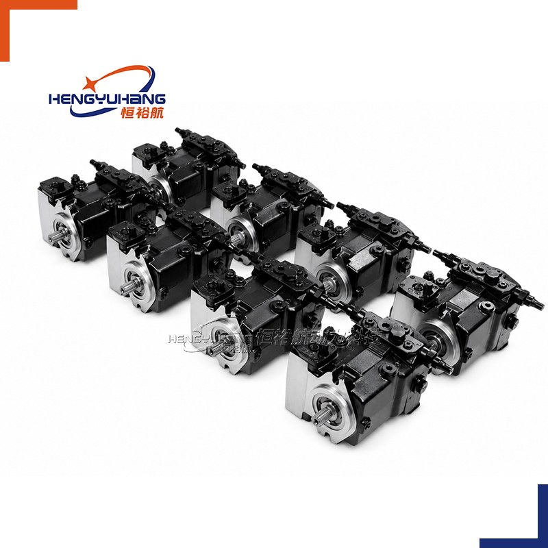
Piston pump
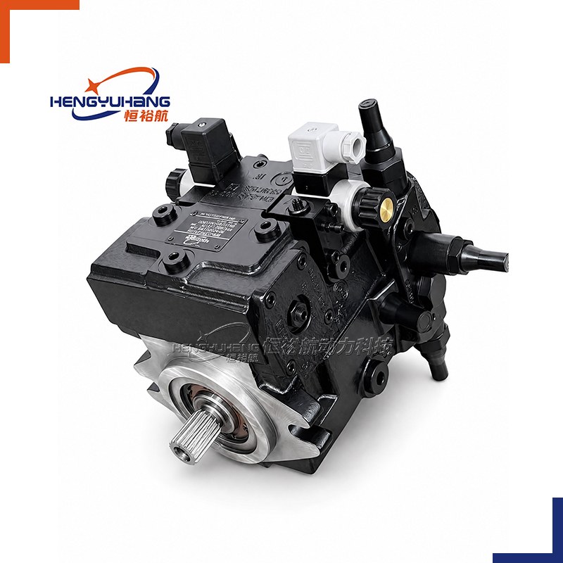
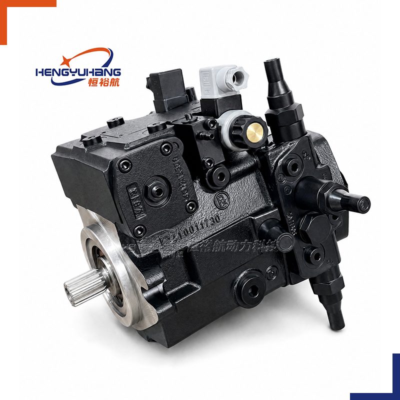
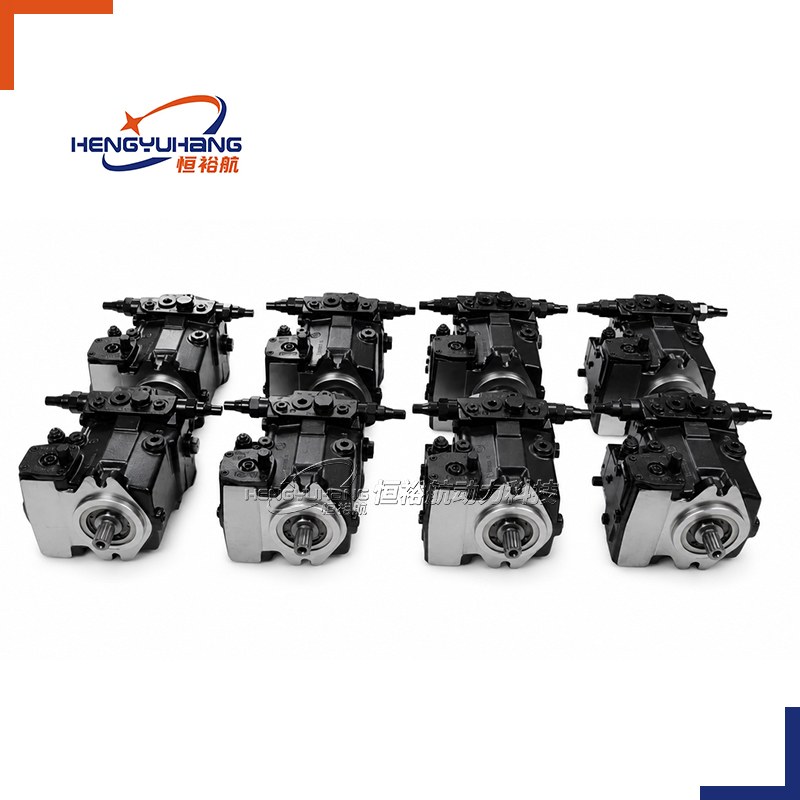
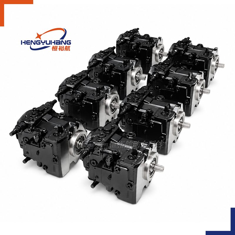
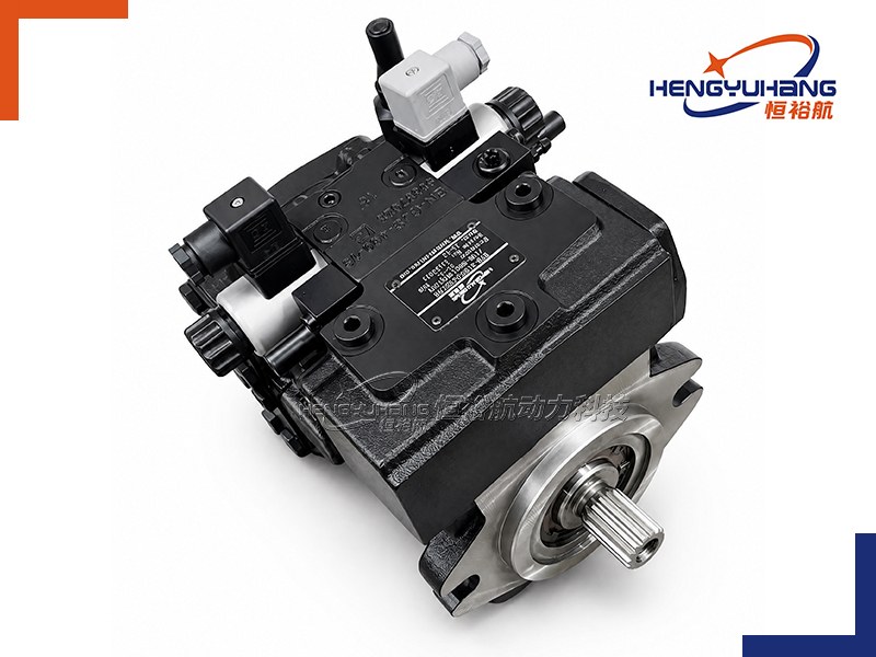
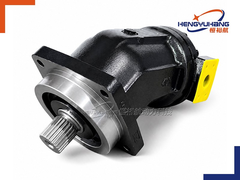
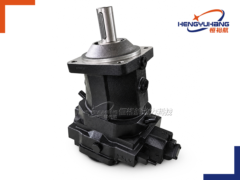
HENGYUHANG Axial piston variable pump HYH10VG series 10
HENGYUHANG HYH10VG Series 10 is a high-performance swashplate axial piston variable displacement pump with an integrated auxiliary boost pump engineered specifically for closed-circuit hydrostatic transmissions, delivering seamless bidirectional flow reversal, continuous 300 bar working pressure (350 bar peak), and high overall efficiency across mobile and industrial drive systems.
| Applications
Engineered for closed-loop hydrostatic drives in compact construction machinery, mini excavators, skid steer loaders, compact wheel loaders, agricultural harvesters, turf equipment, aerial work platforms, road rollers, and industrial winch transmissions requiring integrated charge oil replenishment, full-torque through-drive compound mounting, and precise hydraulic or electro-proportional displacement control.
| Key Technical Specifications
Product Model: HYH10VG Series 10 (Sizes 18, 28, 45, 63)
Brand Replacement: Bosch Rexroth A10VG Series 10 (Sizes 18, 28, 45, 63; closed circuit), OEM or as requested.
Displacement: Main variable pump: 18.4 / 28.8 / 46.1 / 63.1 cm³/rev; Integrated boost pump: 5.5 / 6.1 / 8.6 / 14.9 cm³/rev
Rotation Direction: Clockwise (R) or Counter-clockwise (L), viewed from drive shaft end
Speed Range: Nominal rating n nom 3,000–4,000 rpm (intermittent limiting speed n max2 up to 3,500–5,200 rpm; minimum speed n min = 500 rpm)
Peak Pressure: Nominal continuous working pressure p nom = 300 bar / Maximum peak pressure p max = 350 bar
- Description
- Tecspecs
- Brand & Reference
- Download HENGYUHANG HYH10VG Axial piston variable pump PDF
- Send an Inquiry
| Overview of HENGYUHANG HYH10VG Series 10 Hydraulic Pumps
The HENGYUHANG HYH10VG Series 10 is a swashplate-design axial piston variable displacement pump designed specifically for closed-circuit hydrostatic transmission systems. Manufactured to serve as a seamless, precision 1:1 drop-in replacement for the global Bosch Rexroth A10VG Series 10 family across frame sizes 18, 28, 45, and 63, this pump converts input mechanical torque into smooth, bidirectional hydraulic fluid power.
Fluid delivery is infinitely variable from zero to maximum flow in either direction. When the cradle swashplate is moved through its neutral center position, the direction of fluid delivery reverses smoothly without external reversing valves. Each pump incorporates an internal gerotor/gear auxiliary boost pump that supplies replenishing fluid to the low-pressure side of the closed circuit and provides pilot control oil. Integrated dual high-pressure relief valves with built-in boost replenishment functions protect the transmission against system overpressure and cavitation, while an adjustable low-pressure boost relief valve maintains optimal circuit backpressure. Equipped with standardized SAE J744 2-hole mounting flanges (101-2 / 127-2), ANSI B92.1a heavy-duty splined drive shafts, high-pressure SAE J518 code 62 metric working ports, and multi-pump through-drive configurations, the HYH10VG pump delivers uncompromised reliability, compact installation, and exceptional power density.
| Dimension of HENGYUHANG HYH10VG Series 10 Hydraulic Pumps
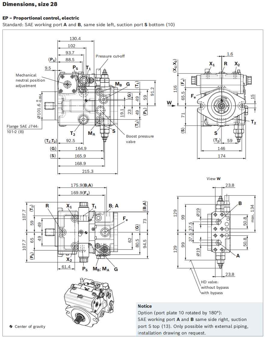
| Mechanical Installation Interface Specifications
| Frame Size (HYH10VG) | 2-Hole Mounting Flange (SAE J744) | Drive Shaft (Splined ANSI B92.1a) | Working Ports A & B (High-Pressure Series) | Suction Port S (DIN 3852) | Case Drain Ports T1 / T2 (DIN 3852) | Boost Inlet Port G (DIN 3852) |
|---|---|---|---|---|---|---|
| HYH10VG18 | SAE 101-2 (B) Spigot Ø101.6 mm | S: 7/8 in 13T 16/32DP (Tolerance class 5) | Threaded Port M27×2 (16 deep; 350 bar peak; Port plate 16) | Threaded Port M26×1.5 (16 deep; 5 bar) | Drain T1 / T2: M18×1.5 (12 deep; 3 bar) | M14×1.5 (12 deep; 25 bar) |
| HYH10VG28 | SAE 101-2 (B) Spigot Ø101.6 mm | S: 1 in 15T 16/32DP; T: 1 1/4 in 14T 12/24DP | SAE J518 3/4 in (Metric thread M10×1.5, 17 deep; Port plate 10/13) | Threaded Port M33×2 (18 deep; 5 bar) | Drain T1 / T2: M22×1.5 (15 deep; 3 bar) | M18×1.5 (12 deep; 40 bar) |
| HYH10VG45 | SAE 101-2 (B) Spigot Ø101.6 mm | S: 1 in 15T 16/32DP; T: 1 1/4 in 14T 12/24DP | SAE J518 3/4 in (Metric thread M10×1.5, 17 deep; Port plate 10/13) | Threaded Port M33×2 (18 deep; 5 bar) | Drain T1 / T2: M22×1.5 (15 deep; 3 bar) | M18×1.5 (12 deep; 40 bar) |
| HYH10VG63 | SAE 127-2 (C) Spigot Ø127.0 mm | S: 1 1/4 in 14T 12/24DP; T: 1 3/8 in 21T 16/32DP | SAE J518 3/4 in (Metric thread M10×1.5, 17 deep; Port plate 10/13) | Threaded Port M33×2 (18 deep; 5 bar) | Drain T1 / T2: M22×1.5 (15 deep; 3 bar) | M18×1.5 (12 deep; 40 bar) |
| Auxiliary Control & Measuring Ports (All Sizes)
Air bleed port R: M12×1.5 (12 deep; 3 bar).
Control pressure ports X1, X2: M12×1.5 (12 deep; 25/40 bar).
Optional stroking chamber ports X3, X4: M10×1 (Size 28, 45) / M12×1.5 (Size 63).
Pressure measuring ports MA, MB (high-pressure lines A/B): M12×1.5 (12 deep; 350 bar peak).
Pilot pressure port PS: M12×1.5 (Size 18) / M14×1.5 (Sizes 28, 45, 63).
External boost pressure filter ports Fe (outlet) & Fa (inlet): M18×1.5 (12 deep; 40 bar).
| Pump Installation Specifications
| Complete Ordering Code Structure
HYH10V−G−[Size]−[Control]−[Cut-off]−[Neutral]−[Stroke]−[Port X]−[DA]/10 [Rotation]−[Seals][Shaft][Flange][Ports][Boost][Through Drive]−[Valve][Filter][Connector][Flush]−[Option]
| Position | Code Segment | Available Designations & Options | Technical Description & Functional Purpose |
|---|---|---|---|
| 01 | Axial Piston Unit | HYH10V / A10V | Swashplate design, variable displacement, nominal pressure 300 bar, peak 350 bar |
| 02 | Operating Mode | G | Pump, closed-circuit hydrostatic drive |
| 03 | Geometric Size | 18, 28, 45, 63 | Geometric displacement in cm³/rev (18.4, 28.8, 46.1, 63.1) |
| 04 | Control Devices | HD3; HW; DA1 / DA2; DG; EP3 / EP4; EZ1 / EZ2; ET3 / ET4 / ETA / ETB; ED2 / ED4 | HD3: Proportional control, hydraulic, pilot-pressure related with inlet filter in P, X1, X2; HW: Proportional control, hydraulic, mechanical servo with control lever; DA1 / DA2: Automatic control, speed-related (12V DC / 24V DC); DG: Hydraulic control, direct operated; EP3 / EP4: Proportional control, electric with proportional solenoids (12V DC / 24V DC); EZ1 / EZ2: Two-point control, electric with switching solenoids (12V DC / 24V DC); ET3 / ET4 / ETA / ETB: Electronic direct-operated control via pressure-reducing valves (BODAS compatible); ED2 / ED4: Electric pressure controller, negative control (24V DC) |
| 05 | Pressure Cut-Off | Blank / D | Blank: Without pressure cut-off; D: With integrated mechanical pressure cut-off valve |
| 06 | Neutral Position Switch | Blank / L | Blank: Without switch; L: Neutral position switch with DEUTSCH connector (for HW control) |
| 07 | Mechanical Stroke Limiter | Blank / M | Blank: Without stroke limiter; M: Mechanical stroke limiter, externally adjustable |
| 08 | Stroking Chamber Ports | Blank / T | Blank: Without ports X3, X4; T: With external stroking chamber ports X3, X4 |
| 09 | DA Control Valve | 1, 2, 3R, 3L, 7, 8 | Speed-dependent regulating valve (fixed, lever adjustable, or with hydraulic inch valve) |
| 10 | Series | 10 | Series 1, Index 0 |
| 11 | Direction of Rotation | R, L | Clockwise (R) or Counter-clockwise (L), viewed facing drive shaft |
| 12 | Sealing System | N | NBR (nitrile rubber) dynamic seals with FKM fluorocarbon shaft seal ring |
| 13 | Drive Shaft Type | S, T | S: Splined shaft ANSI B92.1a (standard); T: Reinforced splined shaft for tandem pumps |
| 14 | Mounting Flange | C | SAE J744 2-hole mounting flange (101-2 for Sizes 18–45; 127-2 for Size 63) |
| 15 | Working Line Ports | 10, 13, 16 | 10: SAE ports A & B left, S bottom; 13: SAE ports A & B right, S top; 16: Threaded ports (Size 18) |
| 16 | Boost Pump Execution | F, N, K | F: Integrated boost pump; N: Without boost pump, no through drive; K: Without boost pump, with through drive |
| 17 | Through-Drive Flange | 00, 01, 52, 02, 04, 07 | 00: None; 01: SAE A 82-2 (9T); 52: SAE A (11T); 02: SAE B 101-2 (13T); 04: SAE B (15T); 07: SAE C 127-2 (14T) |
| 18 | High-Pressure Relief Valve | 3, 5, 4, 6 | Direct-operated relief valves: 3/5 (250–320 bar); 4/6 (100–250 bar); 5/6 with bypass |
| 19 | Filtration Arrangement | S, D, E | S: Suction line filtration; D: Pressure line filtration (ports Fe/Fa); E: External boost supply |
| 20 | Connector for Solenoid | Blank / P / Q | Blank: Purely hydraulic; P: DEUTSCH DT04-2P; Q: DEUTSCH with suppressor diode |
| 21 | Flushing Valve | Blank / 1 / 3 | Blank: Without flushing valve; 1: SAE port block interface; 3: Metric threaded ports |
| 22 | Special Version | -0 / -S | -0: Standard production version; -S: Special custom-engineered execution |
| Reading Your Replacement Code
| Rexroth OEM Model Code | HENGYUHANG Drop-In Code | Displacement | Control Mechanism | Shaft & Flange Specification | Porting & Auxiliary Equipment |
|---|---|---|---|---|---|
| A10VG18EP3/10R-NSC16F003S-0 | HYH10VG18EP3/10R-NSC16F003S-0 | 18.4 cm³/rev | Electric proportional (12V) | ANSI 7/8" 13T spline, SAE 101-2 flange | Threaded ports, boost pump, 250–320 bar relief |
| A10VG28HW/10R-NSC10F013S-0 | HYH10VG28HW/10R-NSC10F013S-0 | 28.8 cm³/rev | Mechanical servo with lever | ANSI 1" 15T spline, SAE 101-2 flange | SAE 3/4" ports, SAE A through drive, suction filter |
| A10VG45EP4D/10R-NSC10F023S-0 | HYH10VG45EP4D/10R-NSC10F023S-0 | 46.1 cm³/rev | Electric proportional (24V) + cut-off | ANSI 1" 15T spline, SAE 101-2 flange | SAE 3/4" ports, SAE B through drive, suction filter |
| A10VG45DA2D/10R-NSC10F003S-0 | HYH10VG45DA2D/10R-NSC10F003S-0 | 46.1 cm³/rev | Speed-dependent DA (24V) + cut-off | ANSI 1" 15T spline, SAE 101-2 flange | SAE 3/4" ports, without through drive |
| A10VG63HD3D/10R-NSC10F043S-0 | HYH10VG63HD3D/10R-NSC10F043S-0 | 63.1 cm³/rev | Hydraulic pilot control + cut-off | ANSI 1 1/4" 14T spline, SAE 127-2 flange | SAE 3/4" ports, SAE B (15T) through drive |
Technical Specifications of HENGYUHANG HYH10VG Series 10 (Closed-Circuit, Sizes 18–63)
4.1 Frame Size Performance Matrix (Data at optimum viscosity νₒₚₜ=36…16 mm²/s, mineral oil ρ=0.88 kg/L)
| Performance Parameter | Unit | HYH10VG18 | HYH10VG28 | HYH10VG45 | HYH10VG63 |
|---|---|---|---|---|---|
| Max Geometric Displacement (Vgₘₐₓ) | cm³/rev | 18.4 | 28.8 | 46.1 | 63.1 |
| Integrated Boost Pump Displacement (Vg_Sp at 20 bar) | cm³/rev | 5.5 | 6.1 | 8.6 | 14.9 |
| Nominal Speed at Vgₘₐₓ (nₙₒₘ) | rpm | 4,000 | 3,900 | 3,300 | 3,000 |
| Limited Maximum Speed (nₘₐₓ₁ at half corner power) | rpm | 4,850 | 4,200 | 3,550 | 3,250 |
| Intermittent Maximum Speed (nₘₐₓ₂ at Δp<300 bar, t<0.1 s) | rpm | 5,200 | 4,500 | 3,800 | 3,500 |
| Minimum Operating Speed (nₘᵢₙ) | rpm | 500 | 500 | 500 | 500 |
| Max Continuous Flow Rate (qV at nₙₒₘ and Vgₘₐₓ) | L/min | 73.6 | 112.3 | 152.1 | 189.3 |
| Continuous Drive Power (P at nₙₒₘ and Δp=300 bar) | kW | 36.8 | 56.2 | 76.1 | 94.7 |
| Continuous Drive Torque (M at Vgₘₐₓ and Δp=300 bar) | Nm | 87.9 | 137.5 | 220.1 | 301.3 |
| Torque at Δp=100 bar | Nm | 29.3 | 45.8 | 73.4 | 100.4 |
| Drive Shaft Torsional Stiffness (Standard Shaft S) | kNm/rad | 20.28 | 32.14 | 53.40 | 78.37 |
| Drive Shaft Torsional Stiffness (Reinforced Shaft T) | kNm/rad | — | — | 73.80 | 92.37 |
| Rotary Moment of Inertia (J_TW) | kg·m² | 0.00093 | 0.00170 | 0.00330 | 0.00560 |
| Maximum Angular Acceleration Limit (α) | rad/s² | 6,800 | 5,500 | 4,000 | 3,300 |
| Housing Case Fluid Volume | L | 0.45 | 0.64 | 0.75 | 1.10 |
| Dry Weight (approx., without through drive) | kg | 18.0 | 25.0 | 27.0 | 39.0 |
4.2 Operating Pressure Boundaries
| Parameter | Value (High-Pressure Side A/B) | Value (Boost Circuit) | Functional Requirement & Operating Rules |
|---|---|---|---|
| Nominal Operating Pressure (pₙₒₘ) | 300 bar (30 MPa) | 20 bar (Size 18) / 25 bar (Sizes 28–63) | Maximum continuous design operating pressure for fatigue life |
| Maximum Peak Pressure (pₘₐₓ) | 350 bar (35 MPa) | 25 bar (Size 18) / 40 bar (Sizes 28–63) | Maximum transient pressure within single operating period (t≤10 s, total ≤300 h) |
| Minimum Pressure on Low-Pressure Side | ≥10 bar above case pressure | — | Prevents cavitation, slipper liftoff, and barrel separation in closed circuit |
| Suction Port Pressure (pₛ at Port S) | — | ≥0.8 bar absolute continuous (≥0.5 bar cold start, t<3 min) | Inlet pressure at boost pump suction; maximum permissible p_S max≤5 bar absolute |
| Rate of Pressure Change (RAₘₐₓ) | 9,000 bar/s | — | Maximum permissible speed of pressure build-up and reduction |
| Differential Case Pressure at Shaft Seal | ≤2.0 bar continuous | Peak p_T peak≤10 bar (t<0.1 s) | Differential pressure between case drain and atmosphere to protect FKM seal |
4.3 Hydraulic Fluid & Temperature Operational Limits
| Fluid Characteristic | Permissible Value | Operational Note |
|---|---|---|
| Recommended Fluid Media | Mineral oil (HLP to DIN 51524) | High-performance anti-wear hydraulic oil |
| Optimum Operating Viscosity (νₒₚₜ) | 16 to 36 mm²/s | Optimal balance of volumetric and mechanical-hydraulic efficiency |
| Continuous Viscosity Range | 10 to 400 mm²/s | Permissible within normal operating temperature limits |
| Minimum Viscosity (νₘᵢₙ) | 7 to 10 mm²/s | Short-term limit (t≤3 min) at p≤0.3⋅pₙₒₘ, Tₘₐₓ=+110 ∘C (FKM seal) measured at port T |
| Maximum Viscosity at Cold Start (νₘₐₓ) | 1,600 mm²/s | Allowed at cold start (p≤50 bar, n≤1,000 rpm, θ_St≥−25 ∘C for FKM, −40 ∘C for NBR) |
| Permissible Fluid Temperature Range | −25 ∘C to +110 ∘C | Operating phase with FKM shaft seal; bearing temperature up to +115 ∘C |
| Cleanliness Class | ISO 4406 Class 20/18/15 | At fluid temperatures +90 ∘C to +115 ∘C, maintain Class 19/17/14 |
| Environmentally Friendly / Synthetic Fluids | HEES, HEPG, HFD | Observe operational limits and deratings in data sheet RE 90225 |
Product Advantages
True Closed-Circuit Swashplate Kinematics
Symmetrical swashplate cradle allows smooth, stepless displacement regulation and instant bidirectional flow reversal when traversing through the center neutral position without external reversing valving.
Integrated High-Capacity Boost Pump
Built-in charge pump automatically supplies replenishing fluid to compensate for motor/pump circuit leakage, continuously flushes the closed loop, and maintains positive control pilot pressure.
Combined High-Pressure & Boost Relief Valves
Direct-operated dual high-pressure relief valves feature an integrated boost suction function, providing fast-acting system overpressure dampening while preventing circuit cavitation during aggressive braking.
Robust Full-Torque Auxiliary Through-Drive
Engineered with heavy-duty through-drive options (SAE A, B, C; 9T, 11T, 13T, 14T, 15T splines), allowing 100% torque transmission for compounding matching secondary pumps (e.g. A10VG + A10VG or gear pumps).
Versatile Modular Control Architectures
Supports mechanical servo lever (HW), electric proportional solenoids (EP), two-point switching (EZ), hydraulic pilot (HD), electronic BODAS (ET), and engine speed-dependent automotive (DA) controls with optional pressure cut-off.
Precision 1:1 OEM Drop-In Compatibility
Exact compliance with Bosch Rexroth A10VG Series 10 mounting flanges, shaft splines, port layouts, and control characteristics guarantees seamless, zero-modification field replacement.
| 6. Interchangeability & Cross Reference
6.1 Direct Replacement Matrix: Bosch Rexroth A10VG to HENGYUHANG HYH10VG
| Rexroth OEM Model | Displacement (Main / Boost) | Mounting Flange (SAE J744) | Drive Shaft (ANSI B92.1a) | Working Port Connections | HENGYUHANG Direct Match |
|---|---|---|---|---|---|
| A10VG18 | 18.4 / 5.5 cm³/rev | SAE 101-2 (B) Ø101.6 mm | 7/8 in 13T 16/32DP (Shaft S) | M27×2 Metric Threaded Ports (Code 16) | HYH10VG18 |
| A10VG28 | 28.8 / 6.1 cm³/rev | SAE 101-2 (B) Ø101.6 mm | 1 in 15T (S) / 1 1/4 in 14T (T) | SAE J518 3/4 in Flange Ports (Code 10/13) | HYH10VG28 |
| A10VG45 | 46.1 / 8.6 cm³/rev | SAE 101-2 (B) Ø101.6 mm | 1 in 15T (S) / 1 1/4 in 14T (T) | SAE J518 3/4 in Flange Ports (Code 10/13) | HYH10VG45 |
| A10VG63 | 63.1 / 14.9 cm³/rev | SAE 127-2 (C) Ø127.0 mm | 1 1/4 in 14T (S) / 1 3/8 in 21T (T) | SAE J518 3/4 in Flange Ports (Code 10/13) | HYH10VG63 |
6.2 Common Modular Control Valve Function Mapping
| Target Rexroth Function | OEM Controller Code | HENGYUHANG Equivalent | Functional Characteristic |
|---|---|---|---|
| Electric Proportional Control | EP3 / EP4 | HYH-EP3 / HYH-EP4 | Proportional displacement via 12V / 24V DC solenoids with internal pilot supply |
| Mechanical Servo Control | HW | HYH-HW | Manual lever angle actuation with hydraulic follow-up servo piston |
| Speed-Dependent Control | DA1 / DA2 | HYH-DA1 / HYH-DA2 | Automatic engine-speed related hydrostatic driving control for mobile machinery |
| Hydraulic Pilot Control | HD3 | HYH-HD3 | Stepless displacement adjustment related to differential pilot pressure |
| Electric Two-Point Control | EZ1 / EZ2 | HYH-EZ1 / HYH-EZ2 | Rapid full displacement bistable switching between swivel angles via solenoids |
| Electronic Direct Control | ET3 / ET4 / ETA / ETB | HYH-ET3 / HYH-ET4 | Proportional pressure-reducing valves directly controlled via electronic BODAS cards |
| Electric Pressure Control | ED2 / ED4 | HYH-ED2 / HYH-ED4 | Negative electric pressure regulation via 4/2-way valve and proportional valve |
| 7. Brand Replacement
Bosch Rexroth (Primary 1:1 direct interchangeability for A10VG Series 10 closed-circuit variable displacement pumps)
Danfoss (Sauer-Danfoss Series 40, Series 90, and H1P closed-circuit pumps engineered upon request)
Eaton, Parker Hannifin, and Bondioli & Pavesi closed-circuit hydrostatic pumps customized to order
| 8. Applications
Mini Excavators & Compact Track Loaders: Hydrostatic track drive and auxiliary swing motor circuit supply.
Skid Steer Loaders & Compact Wheel Loaders: Primary dual-path hydrostatic drive transmission with independent pump control.
Agricultural Harvesters & Mowers: Traction ground drives requiring smooth speed adjustment and dynamic hydrostatic braking.
Road Rollers & Soil Compactors: Closed-circuit vibratory drum drive and hydrostatic propel systems.
Aerial Work Platforms & Scissor Lifts: Infinitely variable traction travel drives with precise micro-inching and creeping control.
Marine & Industrial Winch Systems: Bi-directional hoisting, paying-out, and active heave compensation winch drives.
| 9. Packaging & Shipping
| Packaging Layer | Specification & Protection Material | Safety Standard |
|---|---|---|
| Inner Protection | Corrosion-inhibiting VCI plastic wrap, desiccants, and heavy-duty port thread plugs | Prevents moisture, atmospheric corrosion, and debris contamination |
| Shock Cushioning | Custom-molded high-density expanded polyethylene (EPE) foam enclosure | Absorbs severe multi-axis transit impacts and protects shaft extensions |
| Outer Enclosure | ISPM-15 export-certified solid fumigation-free engineered wooden crate | Structural reinforcement for global ocean, air, and multimodal handling |
| Logistics Options | Express Courier (DHL, FedEx, UPS), Air Freight, LCL/FCL Ocean Cargo, DDP door-to-door | Dispatch in 48–72 hours for standard configurations; tailored tracking provided |
| 10. Why Choose Hengyuhang?
Direct Factory Precision Manufacturing & CNC Excellence: State-of-the-art multi-axis CNC machining centers, precision spherical grinding equipment, and sub-micron gear and bearing fitment (Ra < 0.2 μm) guarantee superior rotary group alignment and low internal leakage.
100% Full-Cycle Multi-Parameter Factory Inspection: Every HYH10VG pump undergoes automated test-bench trials verifying volumetric efficiency (> 94%), continuous and peak pressure hold at 300/350 bar, internal case leakage limits, response hysteresis, and vibration/noise spectra prior to dispatch.
Seamless 1:1 OEM Drop-In Interchangeability: Engineered to match European DIN, ISO, and SAE standards down to the millimeter, allowing immediate replacement of Bosch Rexroth A10VG units with zero pipe rework or bracket modification.
Flexible Engineering Customization & Rapid Prototyping: In-house hydraulic engineering team provides tailored control-valve calibrations, special shaft profiles, auxiliary flushing ports, and rapid prototype turnarounds with minimal MOQ requirements.
Robust Supply Chain, Extensive Inventory & Fast Global Dispatch: Continuous inventory of finished cast bodies, bearing kits, rotary groups, and modular controllers enables standardized orders to ship globally within 48 to 72 hours.
12-Month Comprehensive Warranty & Lifetime Technical Support: All units are backed by an unconditional 12-month factory warranty, 24-hour drawing verification service, and lifetime engineering consultation from certified fluid power specialists.
HENGYUHANG Axial Piston Variable Pump HYH10VG Series 10 (Closed-Circuit Hydrostatic Transmission Pump, 18.00~63.00 cm³/rev) is a high-performance variable-displacement axial piston pump designed in swashplate architecture for hydrostatic transmissions in closed-circuit mobile, stationary, and industrial machinery. Manufactured by Quanzhou Hengyuhang Power Technology Co., Ltd. as an engineered, direct-fit replacement line designed to match the benchmark performance, mounting dimensions, control options, and hydraulic characteristics of the Rexroth A10VG Series 10, the HYH10VG Series incorporates an integrated auxiliary gerotor/gear boost pump for replenishment and pilot oil supply, dual high-pressure relief valves with integrated boost makeup check functions, a built-in boost-pressure relief valve, and standardized rear through-drives for multi-pump auxiliary combinations. All technical ratings, pressure tiers, and dimensional configurations are established according to the official OEM engineering benchmark standard (RE 92750). Fluid flow direction reverses smoothly as the swashplate passes through the neutral center position, delivering stepless variable output proportional to drive speed and swashplate tilt angle. Operating at a continuous nominal pressure of 300 bar (30 MPa / 4,350 psi) and a maximum peak pressure of 350 bar (35 MPa / 5,075 psi) across 4 primary frame sizes—18, 28, 45, and 63 cm³/rev—the HYH10VG Series supports a comprehensive suite of control devices including hydraulic pilot proportional control (HD3), mechanical servo lever control (HW), speed-sensing automotive control (DA1/DA2), direct hydraulic control (DG), electric proportional solenoid control (EP3/EP4), and electric two-point switching (EZ1/EZ2), with optional pressure cut-off (Code D) and mechanical stroke limiters (Code M). Fitted with standardized SAE J744 2-bolt mounting flanges (SAE B for sizes 18~45, SAE C for size 63), ANSI B92.1a splined drive shafts, SAE J518 Code 62 high-pressure split-flange ports, and full-torque through-drive couplings, the HYH10VG Series delivers an ultra-reliable, cost-effective drop-in solution for hydrostatic travel drives, winches, rollers, combine harvesters, and specialized industrial test systems.
| Applications
The HYH10VG Series closed-circuit swashplate variable pump is engineered specifically for hydrostatic closed-loop propel drives, dual-path vehicle transmissions, and bi-directional winch systems requiring smooth reversing and integrated boost management:
Road Construction & Compaction Rollers: Primary closed-circuit hydrostatic propel pump and vibration drum drive for single-drum and tandem asphalt vibratory rollers.
Agricultural Combine Harvesters & Sprayers: Hydrostatic traction drive pump powering front axle hydrostatic wheel motors with DA speed-sensing or HW manual lever control.
Mini Excavators & Compact Track Loaders (CTL): Powers dual-path closed-loop rubber track propel drives and high-flow auxiliary attachment circuits.
Municipal Sweepers & Multi-Purpose Utility Vehicles: Provides stepless hydrostatic ground speed control independent of diesel engine engine working RPM.
Marine & Industrial Winch Hydrostatic Transmissions: Supplies bi-directional closed-circuit high-pressure fluid to radial piston or bent-axis motors for mooring winches, capstans, and anchor hoists.
Underground Mining & Tunnel Utility Shuttles: Heavy-duty hydrostatic powertrain drive with integrated dynamic braking and neutral spring-centering fail-safe operation.
| Key Specifications Overview
| Parameter | Hengyuhang HYH10VG Series 10 Specification (OEM Benchmark Standard) |
|---|---|
| Pump Classification | Axial Piston Variable Displacement Pump in Swashplate Design for Closed Circuits (HYH10VG Series 10) |
| OEM Interchange Reference | Direct dimensional, functional, and hydraulic drop-in replacement for Rexroth A10VG Series 10 |
| Standard Displacement Range | 4 Standard Frame Sizes: 18, 28, 45, and 63 cm³/rev (Geometric max Vg: 18.4, 28.8, 46.1, 63.1 cm³/rev) |
| Integrated Boost Pump Displacements (Vg Sp) | Size 18: 5.5 cm³; Size 28: 6.1 cm³; Size 45: 8.6 cm³; Size 63: 14.9 cm³/rev (at p = 20 bar boost) |
| Nominal Continuous Pressure (pnom) | 300 bar (30 MPa / 4,350 psi) continuous working pressure across working ports A and B |
| Maximum Peak Operating Pressure (pmax) | 350 bar (35 MPa / 5,075 psi) maximum allowable peak pressure within single operating periods (total 300 h) |
| Rate of Pressure Change (RA max) | 16,000 bar/s maximum permissible rate of pressure build-up and reduction across high-pressure circuit |
| Boost Pressure Relief Valve Setting | Standard factory setting: 18 to 25 bar above housing case pressure (depending on control configuration) |
| High-Pressure Relief Valve (HD) Options | Code 3 / 5: Setting range 250~320 bar (with or without bypass); Code 4 / 6: Setting range 100~250 bar (with or without bypass) |
| Rotational Speed Range (at Vg max) | Nominal drive speeds from 3000 rpm (Size 63) up to 4000 rpm (Size 18); Intermittent overspeed up to 5200 rpm (Size 18) |
| Suction Pressure Range (Port S of Boost Pump) | Continuous pS min ≥ 0.8 bar absolute; Cold start pS min ≥ 0.5 bar absolute; Maximum permissible pS max ≤ 5 bar absolute |
| Case Drain Pressure Rating (Ports T1 / T2) | Continuous differential pressure ΔpT cont ≤ 2.0 bar; Momentary pressure peaks pT peak ≤ 10 bar (t < 0.1 s) |
| Piston & Rotary Group Architecture | Swashplate rotary group with steel slipper shoes, dual stroking pistons, centering spring return, and spherical valve plate |
| Mounting Flange Standards | Sizes 18, 28, 45: SAE J744 101-2 (SAE B 2-bolt); Size 63: SAE J744 127-2 (SAE C 2-bolt) |
| Drive Shaft Configurations | ANSI B92.1a splined shafts: Code S (standard for single pump) and Code T (high-torque reinforced for combination pump) |
| Working Fluid Ports (Ports A & B) | Size 18: Threaded DIN 3852 M27×2; Sizes 28 & 45: SAE J518 Code 62 3/4 in (350 bar); Size 63: SAE J518 Code 62 1 in (350 bar) |
| Suction Boost Port (Port S) | Size 18: Threaded DIN 3852 M26×1.5; Sizes 28 & 45: SAE J518 Code 61 1 1/4 in (5 bar); Size 63: SAE J518 Code 61 1 1/2 in (5 bar) |
| Sealing Material System | Code N: NBR (nitrile rubber) body O-rings with premium FKM (fluorocarbon) shaft seal (-25°C to +110°C continuous) |
| Direction of Rotation | Clockwise (Code R) or Counter-Clockwise (Code L), viewed facing input drive shaft (flow direction reversible via swashplate) |
| Operating Viscosity Range | Optimum: νopt = 16 to 36 mm²/s; Permissible: ν = 10 to 400 mm²/s; Max cold start: νmax ≤ 1600 mm²/s |
| Fluid Cleanliness Standard | ISO 4406 Class 20/18/15 minimum (Class 19/17/14 recommended for extended operational service life) |
| Through-Drive Capability | Standard rear through-drive shaft (Codes 01, 52, 02, 04, 07) for mounting auxiliary gear or piston pumps up to 100% torque |
| Technical Performance Matrix Across Available Sizes
| Model Number (Hengyuhang Series) | Displacement (cm³/rev) | Rotational Speed (rpm) | Delivery Flow @ n_nom (L/min) | Drive Power @ 300 bar (kW) | Torque Output (Nm) | Rotary Stiffness (kNm/rad) | Case Fill (L) | Unit Mass (kg, approx) | |||||
|---|---|---|---|---|---|---|---|---|---|---|---|---|---|
| Main Vg | Boost Vg Sp | Nom. n_nom | Lim. n_max1 | Int. n_max2 | @ 100 bar | @ 300 bar | Shaft S | Shaft T | |||||
| HYH10VG-18 | 18.40 | 5.50 | 4000 | 4850 | 5200 | 73.6 | 36.8 | 29.3 | 87.9 | 20.28 | — | 0.45 | 18.0 |
| HYH10VG-28 | 28.80 | 6.10 | 3900 | 4200 | 4500 | 112.3 | 56.2 | 45.8 | 137.5 | 32.14 | — | 0.64 | 25.0 |
| HYH10VG-45 | 46.10 | 8.60 | 3300 | 3550 | 3800 | 152.1 | 76.1 | 73.4 | 220.1 | 53.40 | 73.80 | 0.75 | 27.0 |
| HYH10VG-63 | 63.10 | 14.90 | 3000 | 3250 | 3500 | 189.3 | 94.7 | 100.4 | 301.3 | 78.37 | 92.37 | 1.10 | 39.0 |
| Control Devices & Operating Mechanisms
| Control Code | Control Classification | Control Signal & Supply | Functional Operation & Machine Application |
|---|---|---|---|
| HD3 | Proportional Hydraulic Pilot-Pressure Control | Hydraulic pilot pressure Δpst = 6~18 bar at ports X1 / X2 | Displacement and flow direction are steplessly controlled in proportion to pilot pressure differential; features inlet filtration in P and X1/X2. |
| HW | Proportional Hydraulic Mechanical Servo Control | Manual mechanical control lever with ±33° angular swivel range | Swashplate angle is adjusted via mechanical linkage or push-pull cable with precise mechanical position feedback; optional neutral position switch (Code L). |
| DA1 / DA2 | Automatic Speed-Related Automotive Control | Engine-speed dependent pilot pressure (DA1: 12V / DA2: 24V solenoids) | Automatically increases pump displacement as engine RPM increases; ideal for hydrostatic vehicle propel transmissions (sweepers, loaders, telehandlers). |
| DG | Hydraulic Direct Control | Direct pilot pressure applied to stroking chamber | Direct displacement control via external pilot valve without internal servo feedback; simple, robust configuration for specialized machinery. |
| EP3 / EP4 | Proportional Electric Solenoid Control | Proportional current signal (EP3: 12V DC / EP4: 24V DC, DEUTSCH DT04-2P) | Stepless electric displacement control via electronic proportional solenoids; compatible with RC or BODAS electronic machine controllers. |
| EZ1 / EZ2 | Two-Point Electric Switching Control | On/off electrical switching voltage (EZ1: 12V DC / EZ2: 24V DC) | Rapidly switches pump swashplate between neutral Vg = 0 and preset maximum displacement Vg max for two-speed winch and auxiliary drives. |
| Code D Option | Integrated Pressure Cut-Off | Hydraulic pressure setting via adjustable cut-off spool | Automatically swivels pump back to neutral if system working pressure reaches set limit, preventing high-pressure relief valves from dumping oil and overheating. |
| Mounting Flange, Shaft and Port Specifications
| Size Model | Mounting Flange Standard | Drive Shaft Options (ANSI B92.1a) | Fluid Port Connections (Working, Suction & Case Drain) |
|---|---|---|---|
| HYH10VG-18 | SAE J744 101-2 (SAE B 2-bolt): Pilot Ø101.6 mm (+0/-0.05 mm); Bolt pitch 146 mm; 2 × Ø14.3 mm holes | Code S: Splined shaft ANSI B92.1a 7/8 in 13T 16/32DP (30° pressure angle, flat root side fit, ext. 41.0 mm) | Ports A/B Working: Threaded DIN 3852 M27×2 (16 deep, 350 bar); Port S Suction: DIN 3852 M26×1.5 (16 deep, 5 bar); Drain T1/T2: DIN 3852 M18×1.5 (12 deep); Bleed R: M12×1.5; Stroking X1/X2: M12×1.5 |
| HYH10VG-28 | SAE J744 101-2 (SAE B 2-bolt): Pilot Ø101.6 mm (+0/-0.05 mm); Bolt pitch 146 mm; 2 × Ø14.3 mm holes | Code S: Splined 1 in 15T 16/32DP (ext. 46.0 mm); Code T: Splined 1 1/4 in 14T 12/24DP (reinforced, ext. 56.0 mm) | Ports A/B Working: SAE J518 Code 62 3/4 in (350 bar, M10×1.5, 17 deep); Port S Suction: SAE J518 Code 61 1 1/4 in (5 bar, M10×1.5, 17 deep); Drain T1/T2: DIN 3852 M22×1.5 (12 deep); Gauges MA/MB: M12×1.5 |
| HYH10VG-45 | SAE J744 101-2 (SAE B 2-bolt): Pilot Ø101.6 mm (+0/-0.05 mm); Bolt pitch 146 mm; 2 × Ø14.3 mm holes | Code S: Splined 1 in 15T 16/32DP (ext. 46.0 mm); Code T: Splined 1 1/4 in 14T 12/24DP (reinforced, ext. 56.0 mm) | Ports A/B Working: SAE J518 Code 62 3/4 in (350 bar, M10×1.5, 17 deep); Port S Suction: SAE J518 Code 61 1 1/4 in (5 bar, M10×1.5, 17 deep); Drain T1/T2: DIN 3852 M22×1.5 (12 deep); Gauges MA/MB: M12×1.5 |
| HYH10VG-63 | SAE J744 127-2 (SAE C 2-bolt): Pilot Ø127.0 mm (+0/-0.05 mm); Bolt pitch 181 mm; 2 × Ø17.5 mm holes | Code S: Splined 1 1/4 in 14T 12/24DP (ext. 56.0 mm); Code T: Splined 1 3/8 in 21T 16/32DP (reinforced, ext. 56.0 mm) | Ports A/B Working: SAE J518 Code 62 1 in (350 bar, M12×1.75, 18 deep); Port S Suction: SAE J518 Code 61 1 1/2 in (5 bar, M12×1.75, 18 deep); Drain T1/T2: DIN 3852 M22×1.5 (12 deep); Gauges MA/MB: M12×1.5 |
| Through-Drive Options and Multi-Pump Combinations
| Through-Drive Code | Mounting Flange Standard | Internal Splined Coupling Hub | Typical 2nd Auxiliary Pump Combination |
|---|---|---|---|
| 00 | Without through drive | None (closed rear housing with integrated boost pump) | Single pump standalone closed-circuit operation |
| 01 | SAE J744 82-2 (SAE A 2-bolt) | Spline ANSI B92.1a 5/8 in 9T 16/32DP | Auxiliary micro gear pumps (HYH-HGP-1A, AZPF) for steering or pilot control |
| 52 | SAE J744 82-2 (SAE A 2-bolt) | Spline ANSI B92.1a 3/4 in 11T 16/32DP | Auxiliary medium gear pumps, secondary small open-circuit piston pumps |
| 02 | SAE J744 101-2 (SAE B 2-bolt) | Spline ANSI B92.1a 7/8 in 13T 16/32DP | Secondary closed-circuit HYH10VG-18, open-circuit HYH10VSO-28 |
| 04 | SAE J744 101-2 (SAE B 2-bolt) | Spline ANSI B92.1a 1 in 15T 16/32DP | Secondary HYH10VG-28 or HYH10VG-45, heavy-duty gear pumps |
| 07 | SAE J744 127-2 (SAE C 2-bolt) | Spline ANSI B92.1a 1 1/4 in 14T 12/24DP | Secondary closed-circuit HYH10VG-63 or open-circuit HYH10VSO-71 (Size 63 only) |
| Direct Interchangeability and OEM Replacement Matrix (Rexroth A10VG Series 10)
| Hengyuhang Series Model | OEM Original Rexroth Reference Model | Flange & Shaft Standard | Interchangeability Verification Status |
|---|---|---|---|
| HYH10VG-18 | A10VG 18 EP3 / 10R-NSC16F003S | SAE B 2-Bolt, 7/8 in 13T Spline | 100% Direct Physical & Functional Drop-in Replacement |
| HYH10VG-18 | A10VG 18 HW / 10R-NSC16F003S | SAE B 2-Bolt, 7/8 in 13T Spline | 100% Direct Physical & Functional Drop-in Replacement |
| HYH10VG-28 | A10VG 28 EP3D / 10R-NSC10F003S | SAE B 2-Bolt, 1 in 15T Spline | 100% Direct Physical & Functional Drop-in Replacement |
| HYH10VG-28 | A10VG 28 HW / 10R-NSC10F003S | SAE B 2-Bolt, 1 in 15T Spline | 100% Direct Physical & Functional Drop-in Replacement |
| HYH10VG-45 | A10VG 45 EP4D / 10R-NSC10F003S | SAE B 2-Bolt, 1 in 15T Spline | 100% Direct Physical & Functional Drop-in Replacement |
| HYH10VG-45 | A10VG 45 DA2D / 10R-NSC10F003S | SAE B 2-Bolt, 1 in 15T Spline | 100% Direct Physical & Functional Drop-in Replacement |
| HYH10VG-63 | A10VG 63 EP4D / 10R-NSC10F003S | SAE C 2-Bolt, 1 1/4 in 14T Spline | 100% Direct Physical & Functional Drop-in Replacement |
| HYH10VG-63 | A10VG 63 HW / 10R-NSC10F003S | SAE C 2-Bolt, 1 1/4 in 14T Spline | 100% Direct Physical & Functional Drop-in Replacement |
| Model Coding & Ordering Structure
| Code Field | Field Designation | Available Standard Codes | Technical Definition & Configuration Meaning |
|---|---|---|---|
| [01] Unit Type | Axial Piston Variable Pump | HYH10V | Swashplate variable displacement machine, nominal pressure 300 bar, max 350 bar |
| [02] Mode | Circuit Operation Mode | G | Closed-circuit hydrostatic drive pump |
| [03] Frame Size | Geometric Displacement (cm³) | 18 / 28 / 45 / 63 | Nominal displacement size Vg max in cm³/rev |
| [04] Control Device | Displacement Control Mechanism | HD3 / HW / DA1 / DA2 / DG / EP3 / EP4 / EZ1 / EZ2 | HD: Hydraulic pilot; HW: Manual servo; DA: Automotive speed-sensing; EP: Electric proportional; EZ: Two-point electric |
| [05] Pressure Cut-off | Cut-Off Option | Without code / D | Without code: Without pressure cut-off; Code D: Integrated pressure cut-off valve |
| [06] Neutral Switch | Neutral Position Sensor | Without code / L | Code L: Neutral position switch with DEUTSCH connector (for HW control only) |
| [07] Stroke Limiter | Mechanical Stroke Limit | Without code / M | Code M: Mechanical stroke limiter, externally adjustable |
| [08] Series | Series Designation | 10 | Series 1, Index 0 |
| [09] Rotation | Direction of Rotation | R / L | Code R: Clockwise; Code L: Counter-Clockwise, viewed facing drive shaft |
| [10] Seals | Sealing Material System | N | NBR (nitrile rubber) casing seals with premium FKM shaft seal ring (-25°C to +110°C) |
| [11] Drive Shaft | Input Shaft Configuration | S / T | Code S: ANSI B92.1a splined shaft for single pump; Code T: Reinforced splined shaft for combination pump |
| [12] Mounting Flange | Mounting Flange Style | C | SAE J744 2-bolt (SAE B for sizes 18~45; SAE C for size 63) |
| [13] Port Plate | Working & Suction Port Layout | 10 / 13 / 16 | Code 10: SAE ports A/B same side left, suction bottom; Code 13: SAE ports right, suction top; Code 16: Threaded ports (Size 18) |
| [14] Boost Pump | Charge Pump Configuration | F / N / K | Code F: Integrated boost pump; Code N: Without boost pump; Code K: Without boost pump with through-drive |
| [15] Through Drive | Rear Auxiliary Attachment | 00 / 01 / 52 / 02 / 04 / 07 | Code 00: Without through drive; Codes 01~07: SAE A, SAE B, SAE C auxiliary mounting flanges and hubs |
| [16] Relief Valves | High-Pressure Relief Valve Setting | 3 / 5 / 4 / 6 | Code 3: 250~320 bar without bypass; Code 5: with bypass; Code 4: 100~250 bar without bypass; Code 6: with bypass |
| [17] Filtration | Boost Circuit Filtration | S / D / E | Code S: Suction filtration; Code D: Pressure line filtration (ports Fe/Fa); Code E: External boost supply |
| [18] Connectors | Electrical Valve Connectors | P / Q | Code P: DEUTSCH molded 2-pin DT04-2P without diode; Code Q: DEUTSCH with suppressor diode |
| Technical Performance Matrix Across Available Sizes
| Model Number (Hengyuhang Series) | Displacement (cm³/rev) | Rotational Speed (rpm) | Delivery Flow @ n_nom (L/min) | Drive Power @ 300 bar (kW) | Torque Output (Nm) | Rotary Stiffness (kNm/rad) | Case Fill (L) | Unit Mass (kg, approx) | |||||
|---|---|---|---|---|---|---|---|---|---|---|---|---|---|
| Main Vg | Boost Vg Sp | Nom. n_nom | Lim. n_max1 | Int. n_max2 | @ 100 bar | @ 300 bar | Shaft S | Shaft T | |||||
| HYH10VG-18 | 18.40 | 5.50 | 4000 | 4850 | 5200 | 73.6 | 36.8 | 29.3 | 87.9 | 20.28 | — | 0.45 | 18.0 |
| HYH10VG-28 | 28.80 | 6.10 | 3900 | 4200 | 4500 | 112.3 | 56.2 | 45.8 | 137.5 | 32.14 | — | 0.64 | 25.0 |
| HYH10VG-45 | 46.10 | 8.60 | 3300 | 3550 | 3800 | 152.1 | 76.1 | 73.4 | 220.1 | 53.40 | 73.80 | 0.75 | 27.0 |
| HYH10VG-63 | 63.10 | 14.90 | 3000 | 3250 | 3500 | 189.3 | 94.7 | 100.4 | 301.3 | 78.37 | 92.37 | 1.10 | 39.0 |
| Mounting Flange, Shaft and Port Specifications
| Size Model | Mounting Flange Standard | Drive Shaft Options (ANSI B92.1a) | Fluid Port Connections (Working, Suction & Case Drain) |
|---|---|---|---|
| HYH10VG-18 | SAE J744 101-2 (SAE B 2-bolt): Pilot Ø101.6 mm (+0/-0.05 mm); Bolt pitch 146 mm; 2 × Ø14.3 mm holes | Code S: Splined shaft ANSI B92.1a 7/8 in 13T 16/32DP (30° pressure angle, flat root side fit, ext. 41.0 mm) | Ports A/B Working: Threaded DIN 3852 M27×2 (16 deep, 350 bar); Port S Suction: DIN 3852 M26×1.5 (16 deep, 5 bar); Drain T1/T2: DIN 3852 M18×1.5 (12 deep); Bleed R: M12×1.5; Stroking X1/X2: M12×1.5 |
| HYH10VG-28 | SAE J744 101-2 (SAE B 2-bolt): Pilot Ø101.6 mm (+0/-0.05 mm); Bolt pitch 146 mm; 2 × Ø14.3 mm holes | Code S: Splined 1 in 15T 16/32DP (ext. 46.0 mm); Code T: Splined 1 1/4 in 14T 12/24DP (reinforced, ext. 56.0 mm) | Ports A/B Working: SAE J518 Code 62 3/4 in (350 bar, M10×1.5, 17 deep); Port S Suction: SAE J518 Code 61 1 1/4 in (5 bar, M10×1.5, 17 deep); Drain T1/T2: DIN 3852 M22×1.5 (12 deep); Gauges MA/MB: M12×1.5 |
| HYH10VG-45 | SAE J744 101-2 (SAE B 2-bolt): Pilot Ø101.6 mm (+0/-0.05 mm); Bolt pitch 146 mm; 2 × Ø14.3 mm holes | Code S: Splined 1 in 15T 16/32DP (ext. 46.0 mm); Code T: Splined 1 1/4 in 14T 12/24DP (reinforced, ext. 56.0 mm) | Ports A/B Working: SAE J518 Code 62 3/4 in (350 bar, M10×1.5, 17 deep); Port S Suction: SAE J518 Code 61 1 1/4 in (5 bar, M10×1.5, 17 deep); Drain T1/T2: DIN 3852 M22×1.5 (12 deep); Gauges MA/MB: M12×1.5 |
| HYH10VG-63 | SAE J744 127-2 (SAE C 2-bolt): Pilot Ø127.0 mm (+0/-0.05 mm); Bolt pitch 181 mm; 2 × Ø17.5 mm holes | Code S: Splined 1 1/4 in 14T 12/24DP (ext. 56.0 mm); Code T: Splined 1 3/8 in 21T 16/32DP (reinforced, ext. 56.0 mm) | Ports A/B Working: SAE J518 Code 62 1 in (350 bar, M12×1.75, 18 deep); Port S Suction: SAE J518 Code 61 1 1/2 in (5 bar, M12×1.75, 18 deep); Drain T1/T2: DIN 3852 M22×1.5 (12 deep); Gauges MA/MB: M12×1.5 |
| Direct Interchangeability and OEM Replacement Matrix (Rexroth A10VG Series 10)
| Hengyuhang Series Model | OEM Original Rexroth Reference Model | Flange & Shaft Standard | Interchangeability Verification Status |
|---|---|---|---|
| HYH10VG-18 | A10VG 18 EP3 / 10R-NSC16F003S | SAE B 2-Bolt, 7/8 in 13T Spline | 100% Direct Physical & Functional Drop-in Replacement |
| HYH10VG-18 | A10VG 18 HW / 10R-NSC16F003S | SAE B 2-Bolt, 7/8 in 13T Spline | 100% Direct Physical & Functional Drop-in Replacement |
| HYH10VG-28 | A10VG 28 EP3D / 10R-NSC10F003S | SAE B 2-Bolt, 1 in 15T Spline | 100% Direct Physical & Functional Drop-in Replacement |
| HYH10VG-28 | A10VG 28 HW / 10R-NSC10F003S | SAE B 2-Bolt, 1 in 15T Spline | 100% Direct Physical & Functional Drop-in Replacement |
| HYH10VG-45 | A10VG 45 EP4D / 10R-NSC10F003S | SAE B 2-Bolt, 1 in 15T Spline | 100% Direct Physical & Functional Drop-in Replacement |
| HYH10VG-45 | A10VG 45 DA2D / 10R-NSC10F003S | SAE B 2-Bolt, 1 in 15T Spline | 100% Direct Physical & Functional Drop-in Replacement |
| HYH10VG-63 | A10VG 63 EP4D / 10R-NSC10F003S | SAE C 2-Bolt, 1 1/4 in 14T Spline | 100% Direct Physical & Functional Drop-in Replacement |
| HYH10VG-63 | A10VG 63 HW / 10R-NSC10F003S | SAE C 2-Bolt, 1 1/4 in 14T Spline | 100% Direct Physical & Functional Drop-in Replacement |
 WhatsApp
 Email
 +86 19918575358