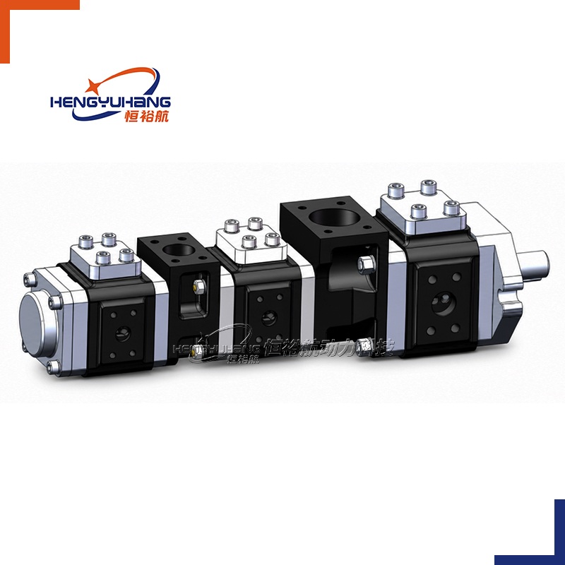
Gear pump
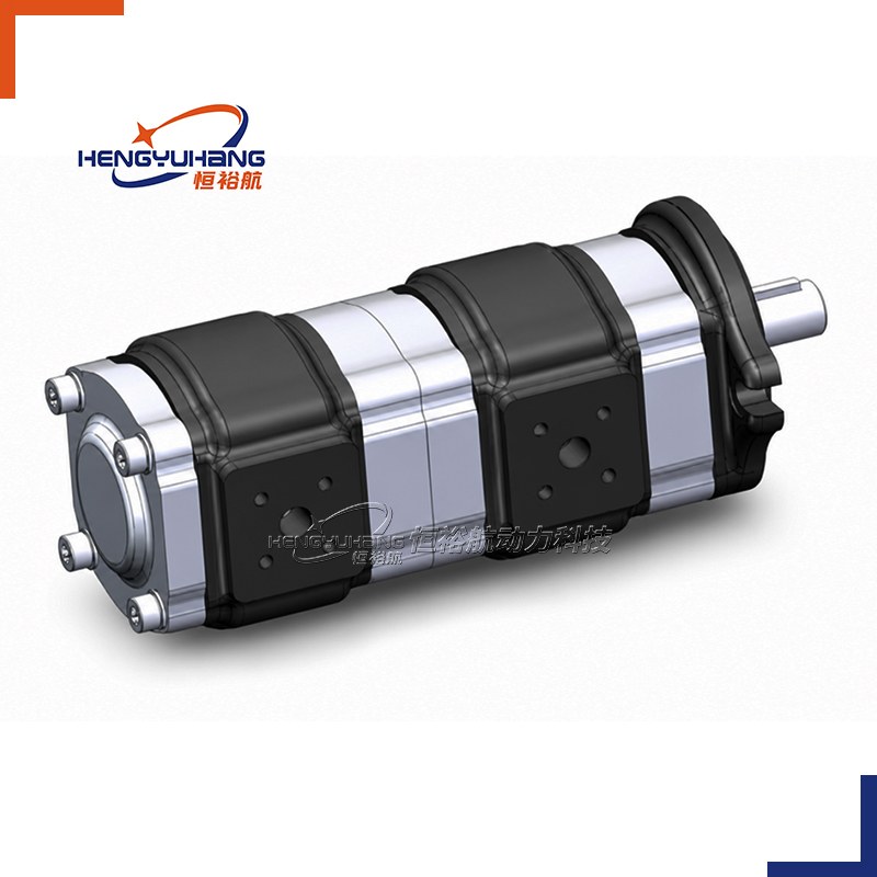
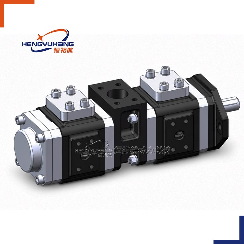
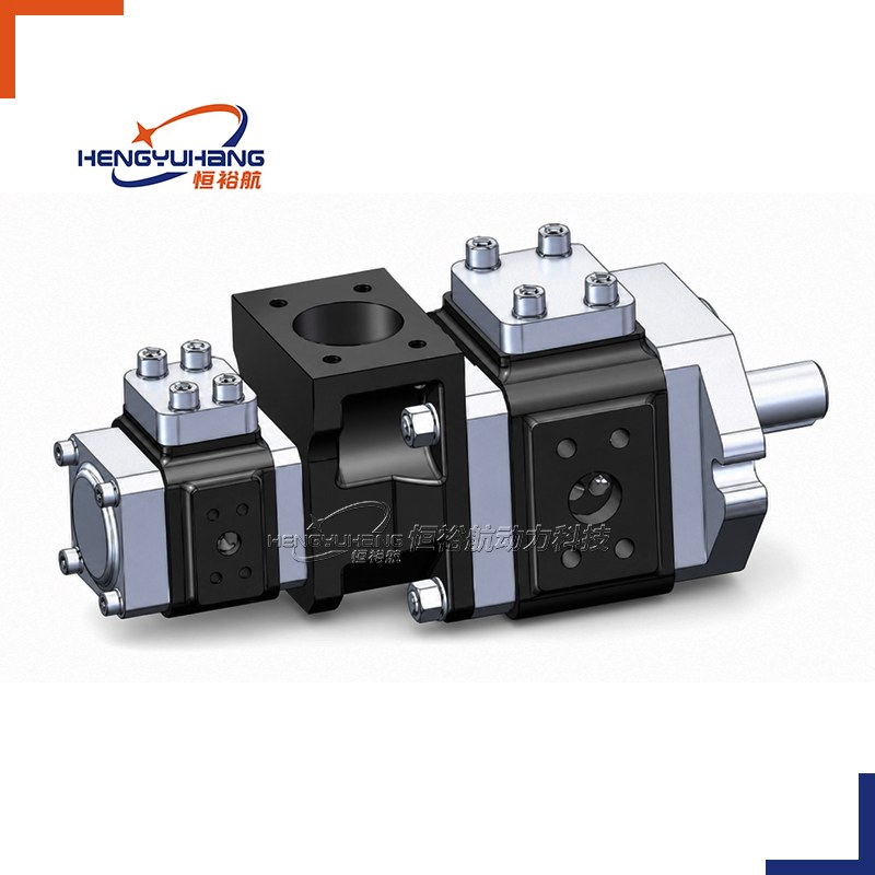
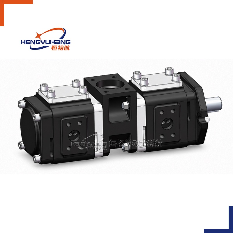
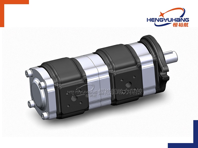
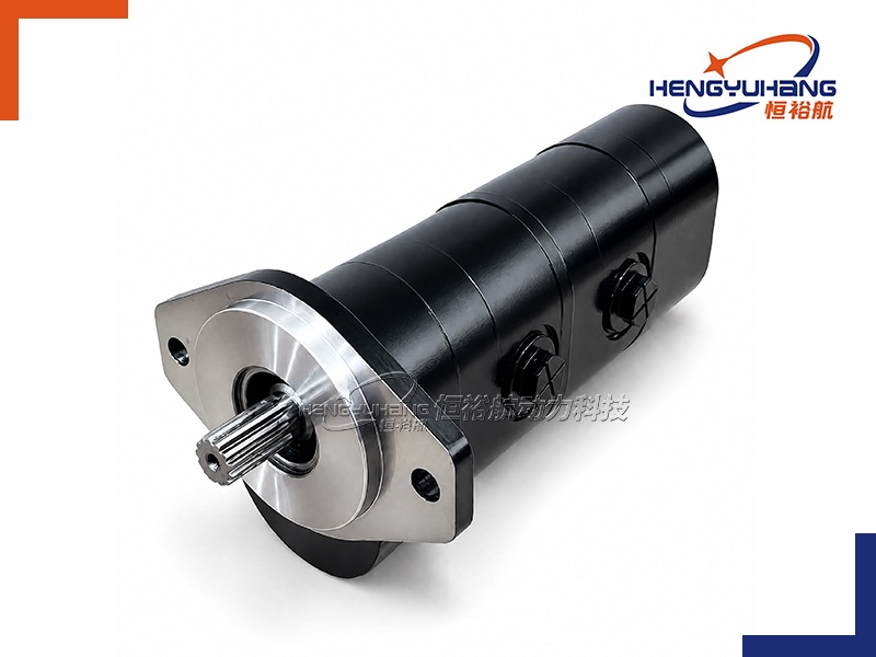
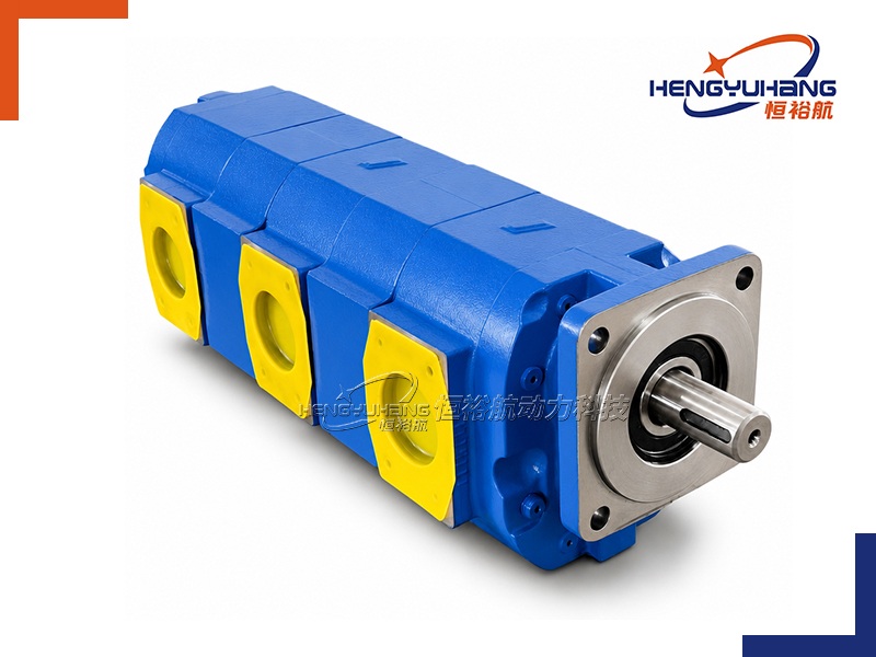
Multi-stage pump Internal Hydraulic Gear Pump 2APHF SAE A 2-Bolt Oval Flange Series
Engineered with active radial and axial gap compensation and conjugate internal gear geometry, the HENGYUHANG 2APHF multi-stage internal hydraulic gear pump delivers whisper-quiet, virtually pulsation-free fluid power with operating pressures up to 320 bar (4,640 psi / 32 MPa) and volumetric efficiency exceeding 92%.
| Applications
Engineered for servo-electric and variable-speed industrial machinery, this multi-stage internal gear pump powers plastic injection molding machines, CNC hydraulic press brakes, die-casting machines, and automated machine tool power packs. Its multi-stage through-drive architecture enables independent multi-circuit delivery from a single prime mover, while the universal SAE A 2-bolt oval flange provides seamless 1:1 mechanical drop-in replacement across European internal gear pump platforms.
| Key Technical Specifications
Product Model: Hengyuhang Multi-Stage Internal Hydraulic Gear Pump 2APHF SAE A 2-Bolt Oval Flange Series
Brand Replacement: ECKERLE (EIPS1, EIPS2), HOERBIGER (HQI2, HQI3), HYDAC (PGI100, PGI101, PGI102) OEM or as requested.
Displacement: 4.2 to 25.2 cm³/rev per stage (combined tandem displacements up to 50.4 cm³/rev)
Rotation Direction: Clockwise (R / D), counter-clockwise (L / S)
Speed Range: Min. speed 200 r/min; Max. speed 2500 to 3000 r/min
Peak Pressure: Up to 32 MPa (320 bar / 4,640 psi)
- Description
- Tecspecs
- Brand & Reference
- Download HENGYUHANG 2APHF Internal Hydraulic Gear Pump PDF
- Send an Inquiry
| Overview of HENGYUHANG 2APHF Multi-Stage Series
The HENGYUHANG 2APHF Multi-Stage Series represents advanced engineering in high-pressure, low-noise internal gear hydraulic pumps. Utilizing a precision internal gear conjugate profile, a crescent seal partition, and active dual gap compensation (both axial thrust plate compensation and radial seal segment compensation), the 2APHF pump counteracts internal deflections under fluctuating system pressures and operating temperatures. This maintains internal clearances and enables volumetric efficiencies up to 93% while keeping acoustic noise levels between 53 and 61 dB(A).
The multi-stage through-drive configuration allows two or more 2APHF pumping elements to be coupled in tandem on a single drive axis, powering independent high-pressure circuits (such as clamp, injection, and auxiliary core-pulling functions in molding machines) with common or separate suction ports. Built with a universal SAE A 2-bolt oval mounting flange (pilot Ø 82.55 mm / 3.25" with 106.4 mm / 4.189" bolt centers) and standardized cylindrical keyed or SAE involute splined drive shafts, the 2APHF multi-stage series serves as a 1:1 OEM drop-in replacement for ECKERLE EIPS1 / EIPS2, HOERBIGER HQI2 / HQI3, and HYDAC PGI100 / PGI101 / PGI102 series without requiring piping redesign or mounting bracket modification.
| Dimension of HENGYUHANG 2APHF Multi-Stage Series
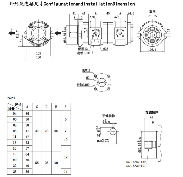
| Interface Data Needed with the Drawing (Dimensional Reference Table)
| Interface Parameter | Engineering Specification & Dimensional Standard | Notes / Tolerance |
|---|---|---|
| Mounting Flange | SAE "A" 2-bolt oval mounting flange (SAE J744 standard) | Standard Catalogue Code A2 |
| Flange Centring Pilot | Ø 82.55 mm (3.250 in) | Pilot tolerance h8 (-0.05 mm), pilot depth 6.0 mm (0.236 in) |
| 2-Bolt Ear Spacing | 106.4 mm (4.189 in) center distance | Standard 2-bolt oval mounting pattern |
| Mounting Bolt Holes | 2 × Ø 11.0 mm (0.433 in) through clearance holes | Suitable for 3/8"-16 UNC or M10 high-tensile bolts |
| Primary Drive Shaft | Cylindrical keyed shaft Ø 20.0 mm (-0.007 / -0.020 mm) with 6.0 mm key | Optional: SAE 16/32-13T or 16/32-10T involute spline |
| Shaft Extension Length | 41.0 mm (1.614 in) from mounting pilot face | Standardized coupling engagement length |
| Multi-Stage Through-Drive | Internal precision splined through-drive coupling | Connects front and rear internal gear rotor assemblies |
| Suction Ports (Inlet, S) | 4-bolt square/rectangular flange (C = 40 mm / D = 20 mm or C = 55 mm / D = 26 mm) | Separate suction ports or shared common suction block |
| Pressure Ports (Outlet, P) | 4-bolt high-pressure flange with central discharge orifice (Ø 5 to 14 mm) | 4-M6 threaded holes depth 13 mm per stage |
| Housing Construction | High-tensile spheroidal graphite ductile cast iron body | Resists high cyclic impulse pressures |
| Seals Material | Standard: NBR Buna-N (-20 °C to +80 °C); Optional: FKM Viton (-10 °C to +150 °C) | Fluoropolymer backup rings for high-pressure gap sealing |
| Flange Fastening Torque | 60 ± 5 N·m (531 ÷ 575 lbf·in) | Fastened evenly to electric motor face or bell-housing |
| Port Flange Screw Torque | M6: 12 ± 1 N·m (106 lbf·in); M8: 28 ± 2 N·m (248 lbf·in) | Metric grade 8.8 or 10.9 socket head cap screws |
| Pump Installation Specifications HENGYUHANG 2APHF Multi-Stage Series
| Comprehensive Ordering Code Breakdown (Hengyuhang 2APHF Multi-Stage Structure)
Code structure — reference: 2APHF−D1/D2−R−K−A2−F1−N−M
| Code Position | Meaning & Available Values |
|---|---|
| 2APHF | Series designation (Group 2 High-Pressure Low-Noise Internal Gear Pump Platform) |
| D1 (Front Stage Displacement) | Nominal displacement: 04 (4.2), 05 (5.4), 06 (6.4), 08 (7.9), 11 (10.9), 13 (13.3), 16 (15.8), 19 (19.3), 20 (20.1), 22 (22.2), 25 (25.2 cm³/rev) |
| D2 (Rear Stage Displacement) | Selected from identical 2APHF range (4.2 to 25.2 cm³/rev) |
| R (Rotation Direction) | R = Clockwise (viewed from shaft end); L = Counter-clockwise |
| K (Drive Shaft Code) | K = Cylindrical keyed shaft (Ø 20 mm, 6 mm key); S1 = SAE 16/32-13T spline; S2 = SAE 16/32-10T spline |
| A2 (Mounting Flange) | A2 = SAE "A" 2-bolt oval mounting flange (pilot Ø 82.55 mm, 106.4 mm centers) |
| F1 (Port Configuration) | F1 = Standard 4-bolt metric flanged ports; F2 = Threaded BSPP / SAE straight thread O-ring ports |
| N (Seals Compound) | N = NBR Buna-N (-20 °C to +80 °C); V = FKM Viton (-10 °C to +150 °C) |
| M (Multi-Stage Execution) | D = Tandem double pump assembly; T = Triple pump assembly |
| Reading Your Replacement Code
| Code Segment | Example Value | Meaning & Configuration |
|---|---|---|
| Series & Displacements | 2APHF-16/08 | Multi-Stage Internal Gear: Front Stage (15.8 cm³/rev) + Rear Stage (7.9 cm³/rev) |
| Rotation | R | Clockwise rotation when looking at drive shaft end |
| Drive Shaft | K | Cylindrical keyed shaft Ø 20.0 mm with 6.0 mm parallel key |
| Mounting Flange | A2 | SAE "A" 2-bolt oval flange (Ø 82.55 mm pilot, 106.4 mm bolt spacing) |
| Port Dimensions | F1 | Standard 4-bolt flanged suction and pressure connections |
| Seal Compound | N | Nitrile butadiene rubber (NBR) seals |
| Assembly Style | D | Dual-stage tandem assembly with independent pressure circuits |
| Techspecs of HENGYUHANG 2APHF Multi-Stage Series
| Technical Performance Across Displacements (Per Stage 2APHF Architecture)
Note: Test conditions: mineral oil ISO VG 46, T = 50 °C, ν = 30 mm²/s, n = 1,450 r/min.
| Model Code | Displacement (cm³/rev) | Rated Pressure (MPa / bar) | Peak Pressure (MPa / bar) | Speed Range (r/min) | Volumetric Eff. (%) | Noise Level @ 1450 rpm, 25 MPa (dB) | Weight (kg) |
|---|---|---|---|---|---|---|---|
| 2APHF-04 | 4.2 | 28 / 280 | 32 / 320 | 200 – 3,000 | 88 | 53 | 2.9 |
| 2APHF-05 | 5.4 | 28 / 280 | 32 / 320 | 200 – 3,000 | 91 | 53 | 2.9 |
| 2APHF-06 | 6.4 | 28 / 280 | 32 / 320 | 200 – 3,000 | 92 | 54 | 3.0 |
| 2APHF-08 | 7.9 | 28 / 280 | 32 / 320 | 200 – 3,000 | 92 | 55 | 3.1 |
| 2APHF-11 | 10.9 | 28 / 280 | 32 / 320 | 200 – 3,000 | 92 | 56 | 3.3 |
| 2APHF-13 | 13.3 | 28 / 280 | 32 / 320 | 200 – 3,000 | 92 | 57 | 3.5 |
| 2APHF-16 | 15.8 | 28 / 280 | 32 / 320 | 200 – 3,000 | 92 | 58 | 3.6 |
| 2APHF-19 | 19.3 | 28 / 280 | 30 / 300 | 200 – 2,800 | 93 | 58 | 3.8 |
| 2APHF-20 | 20.1 | 25 / 250 | 30 / 300 | 200 – 2,800 | 93 | 59 | 4.0 |
| 2APHF-22 | 22.2 | 25 / 250 | 30 / 300 | 200 – 2,800 | 93 | 59 | 4.0 |
| 2APHF-25 | 25.2 | 25 / 250 | 28 / 280 | 200 – 2,500 | 93 | 60 | 4.2 |
Note: Noise measurement condition: Sound pressure level measured in an anechoic chamber at 1.0 m distance per DIN 45635 part 26.
| Operating Conditions & Fluid Compatibility
| Parameter | Permissible Operating Range | Recommended Optimal Target |
|---|---|---|
| Hydraulic Fluid | Mineral oil-based hydraulic fluids (HL / HLP per DIN 51524) | High-performance anti-wear hydraulic oil |
| Operating Viscosity | 10 to 300 mm²/s (cSt) | 20 to 100 mm²/s (cSt) |
| Max. Starting Viscosity | Up to 2000 mm²/s at cold start (p < 10 bar) | Allow warm-up cycle before applying full pressure |
| Fluid Temperature (NBR) | -20 °C to +80 °C (-4 °F to +176 °F) | +30 °C to +60 °C (+86 °F to +140 °F) |
| Fluid Temperature (FKM) | -10 °C to +150 °C (+14 °F to +302 °F) | For synthetic esters and high-temperature duties |
| Inlet Pressure | 0.8 to 2.0 bar absolute (11.6 to 29.0 psi) | Recommended suction depression < 0.2 bar |
| Cleanliness Class | ISO 4406 Class 19/17/14 (NAS 1638 Class 8) | Extends internal crescent and tooth face service life |
Advantages
Whisper-Quiet Operation (53 to 61 dB)
Conjugate internal gear meshing and crescent partition eliminate trapped fluid compression, significantly reducing airborne and structure-borne noise compared to external gear units.
Dual Gap Compensation Technology
Integrated axial compensation plates and radial seal segments actively counteract pressure-induced micro-deflections, maintaining volumetric efficiency above 92% across variable speeds and thermal cycles.
Multi-Stage Multi-Circuit Capability
Compact modular through-drive design allows multiple pump stages to be driven from a single electric motor or servo axis, supplying independent high-pressure and low-pressure hydraulic circuits without cross-talk.
Low Pressure Pulsation
Smooth internal tooth engagement minimizes flow ripple to less than 2%, preventing hydraulic shock in servo valves, proportional valves, and precision actuator circuits.
Direct 1:1 OEM Drop-In Replacement
Standard SAE A 2-bolt oval flange (Ø82.55 mm pilot, 106.4 mm bolt spacing) and standardized port interfaces match Eckerle, Hoerbiger, and Hydac dimensions for direct replacement.
Wide Speed Range Compatibility
Stable suction and pressure performance from low speeds (200 r/min) up to 3000 r/min, making it well suited for modern variable-speed servo-electric drive systems.
Reference
Multi-Stage Architecture & Displacements
Series Designation: HENGYUHANG Multi-Stage Internal Hydraulic Gear Pump 2APHF SAE A 2-Bolt Oval Flange Series
Modular Stage Platform: Group 2 internal gear platform with 11 standardized displacement sizes (4.2, 5.4, 6.4, 7.9, 10.9, 13.3, 15.8, 19.3, 20.1, 22.2, 25.2 cm³/rev per stage).
Multi-Stage Combinations: Dual tandem (2APHF+2APHF) or triple pump configurations with independent or shared suction ports.
Mounting Standard: SAE A 2-Bolt Oval Flange (Pilot Ø82.55 mm / 3.250" h8, 106.4 mm / 4.189" bolt centers).
Drive Shaft: Cylindrical keyed shaft Ø20 mm (Code K), SAE 16/32-13T spline (Code S1), or SAE 16/32-10T spline (Code S2).
Comprehensive Interchangeability & Replacement Matrix
The HENGYUHANG 2APHF Multi-Stage Series provides 1:1 drop-in replacement compatibility across the following designated international internal gear pump brands and series:
ECKERLE: EIPS1, EIPS2 series internal gear pumps (and EIPS3 series combinations)
HOERBIGER: HQI2, HQI3 series high-pressure internal gear pumps
HYDAC: PGI100, PGI101, PGI102 series low-noise internal gear pumps
Brand Replacement
The HENGYUHANG 2APHF Multi-Stage Series is precision-engineered as a direct 1:1 drop-in replacement for premier European internal hydraulic gear pumps, including the ECKERLE EIPS1/EIPS2 series, HOERBIGER HQI2/HQI3 series, and HYDAC PGI100/PGI101/PGI102 series. Every multi-stage unit undergoes 100% computerized factory testing to verify volumetric efficiency (>92%), mechanical efficiency, multi-circuit pressure hold up to 320 bar, and acoustic emission levels across variable speed profiles. Utilizing standard SAE A 2-bolt oval flange dimensions (pilot Ø82.55 mm, 106.4 mm center distance), standard shaft extensions, and matching flanged port geometries, Hengyuhang pumps allow equipment manufacturers and maintenance teams to perform direct field replacements without piping modification, bell-housing re-machining, or servo drive recalibration. Custom stage displacement pairings and shared or independent suction port configurations are fully supported.
Applications
Plastic Injection Molding Machines: Servo-driven multi-circuit hydraulic power packs supplying independent clamping, injection, and core-pulling functions.
CNC Hydraulic Press Brakes & Bending Machines: Precision ram synchronization and pressure-holding circuits requiring low pulsation and quiet operation.
Die-Casting & Metal-Forming Machinery: Auxiliary accumulator charging, cooling, and high-response proportional hydraulic circuits.
Industrial Automation & Robotics: Compact hydraulic power units for automated transfer lines, clamping fixtures, and test benches.
Testing & Laboratory Equipment: Low-noise test rigs requiring smooth flow and minimal pressure ripple.
Package & Shipping
| Packaging Type | Reinforced export corrugated carton with custom molded shock-absorbing foam inserts; sea-freight orders packed in fumigation-free wooden cases |
|---|---|
| Port Protection | Heavy-duty threaded plastic port plugs and shaft sleeve protectors installed |
| Corrosion Prevention | External rust-preventive oil coating and vapor-corrosion inhibitor (VCI) polybag wrapping |
| Selling Unit | Single item (MOQ = 1 piece for standard models) |
| Package Dimensions | Approx. 380 mm × 240 mm × 220 mm (varies with stage configuration) |
| Gross Weight | Approx. 7.5 – 12.0 kg (depending on multi-stage displacement combination) |
| Standard Lead Time | 3 – 5 business days for stocked components; 15 – 20 business days for volume OEM production |
| Shipping Methods | Global express air freight (DHL / FedEx / UPS / TNT) for urgent maintenance; Sea freight / Air cargo for wholesale orders |
| OEM & Customization | Private label laser marking, customer part numbering, and custom displacement combinations supported |
Why Choose Hengyuhang?
Direct Factory Precision Manufacturing & CNC Excellence: Manufactured in our state-of-the-art production facility equipped with high-precision 4-axis and 5-axis CNC machining centers, automated gear hobbing, and CNC gear tooth profile grinding (Ra < 0.2 μm) to ensure superior surface finish, ultra-tight internal clearances, and maximum volumetric efficiency.
100% Full-Cycle Multi-Parameter Factory Inspection: Every single pump undergoes computerized testing before packaging, verifying flow rate at rated speed, volumetric efficiency (>92%), mechanical efficiency, continuous and peak pressure hold, internal bypass, and noise spectrum. Zero untested units leave the factory.
Seamless 1:1 OEM Drop-In Interchangeability: Dimensionally matched to European, SAE, and DIN standards, providing 1:1 direct mechanical interchangeability across premier global brands (Eckerle, Hoerbiger, Hydac, etc.) with zero mounting modifications required.
Flexible Engineering Customization & Rapid Prototyping: Supported by a senior fluid power engineering team, offering custom displacement combinations, specialized shaft tapers, splines, integrated priority or relief valves, and non-standard port orientations with rapid sample prototyping and low MOQ requirements.
Robust Supply Chain, Extensive Inventory & Fast Global Dispatch: Extensive raw material stock of high-grade ductile cast iron castings, alloy steel gear sets, and bearing assemblies enables rapid assembly and 48–72 hour dispatch for emergency breakdown replacements, supported by complete export logistics.
12-Month Comprehensive Warranty & Lifetime Technical Support: All pumps are backed by a comprehensive 12-month manufacturer warranty against defects in materials and workmanship, supplemented by 24/7 engineering consultation, CAD drawing verification, and lifecycle technical assistance.
Multi-Stage Internal Hydraulic Gear Pump 2APHF SAE A 2-Bolt Oval Flange Series (4.20~25.20 + 4.20~25.20 cm³/rev) is a high-precision, low-noise multi-stage internal gear pump engineered for energy-efficient industrial hydraulics, electro-hydraulic servo drive systems, injection molding machinery, and high-pressure machine tool power units requiring multi-circuit fluid delivery with exceptionally smooth flow and minimal pressure pulsation. Standardized with an industry-standard SAE J744 SAE A 2-bolt oval mounting flange (centering spigot pilot Ø82.55 mm with tolerance 0/-0.05 mm / 3.250 in, pilot engagement depth 6.0 mm / 0.236 in, and 106.4 mm / 4.188 in bolt centers with 2 × Ø11.0 mm mounting clearance slots), the 2APHF multi-stage series couples modular internal gear pump stages (PHF 2A/2A configuration) on a rigid common drive shaft with an intermediate internal spline connection. Featuring straight-tooth conjugate internal gear profiles with hydrostatically balanced axial and radial gap compensation, the 2APHF series maintains continuous operating pressures up to 280 bar (28 MPa / 4,060 psi) on smaller displacements and 250 bar (25 MPa / 3,625 psi) across mid-to-large sizes, with peak surge pressures reaching 320 bar (32 MPa / 4,640 psi). Offering 11 standardized displacement ratings per stage (4.2, 5.4, 6.4, 7.9, 10.9, 13.3, 15.8, 19.3, 20.1, 22.2, and 25.2 cm³/rev), the combined dual-stage displacement spans 8.40 to 50.40 cm³/rev, delivering total combined hydraulic delivery flows from 12.60 to 75.60 L/min @ 1500 rpm. Characterized by its 180° inline opposite port configuration (2A port architecture) and ultra-low acoustic emissions between 53 and 61 dB(A), the pump maintains stable volumetric efficiencies up to 93% even under low-speed servo operations down to 200 min⁻¹.
| Applications
The 2APHF SAE A 2-bolt oval flange multi-stage internal hydraulic gear pump series is specifically designed for high-performance industrial servo hydraulics and stationary machinery requiring quiet operation, precise low-speed controllability, and independent dual-circuit pressure delivery:
Energy-Saving Plastic Injection Molding Machines: Direct-coupled to permanent magnet synchronous servo motors (PMSM); the front stage supplies controlled high-pressure fluid for mold clamping and injection holding, while the rear stage powers secondary ejector pins, core-pulling slides, and proportional back-pressure circuits with ultra-low noise emissions.
CNC Servo Hydraulic Press Brakes and Bending Machines: Operates smoothly under dynamic variable-speed duty cycles down to 200 rpm without stick-slip or cavitation; provides dual independent circuits to synchronize left and right ram positioning cylinders with micrometer-level repeatable accuracy.
Die-Casting Machines and Metal Extrusion Presses: Operates as an energy-efficient dual-displacement system; both stages combine to deliver high-flow prefill during rapid mold closing, transitioning seamlessly to the primary stage for continuous high-tonnage locking up to 280 bar while unloading the secondary stage.
Precision Machine Tools and Machining Center Lubrication: Powers high-pressure hydraulic workpiece clamping fixtures on stage one while simultaneously supplying clean hydraulic fluid to hydro-static spindle bearings and guideway lubrication systems on stage two.
Automated Handling Systems and Hydraulic Lifts: Delivers virtually pulsation-free hydraulic power to elevator lifting cylinders and AGV scissor mechanisms, ensuring smooth motion profiles and quiet operating environments compliant with indoor industrial acoustic standards.
High-Pressure Industrial Test Benches and Flushing Rigs: Delivers stable, continuous fluid flow with minimal ripple across wide viscosity ranges (10 to 300 mm²/s), serving as the baseline power source for component endurance validation and multi-circuit valve testing.
| Key Specifications Overview
| Parameter | Specification |
|---|---|
| Series Architecture | Modular Multi-Stage Internal Hydraulic Gear Pump (Dual-Stage PHF 2A/2A Series with 180° Opposite Inline Porting) |
| Stage Displacement Sizes (cm³/rev) | 11 Standardized Displacements per stage: 4.2, 5.4, 6.4, 7.9, 10.9, 13.3, 15.8, 19.3, 20.1, 22.2, 25.2 cm³/rev |
| Total Combined Displacement Range | 8.40 ~ 50.40 cm³/rev (modular dual-circuit pairing: V1 + V2) |
| Continuous Operating Pressure (p1) | 280 bar (28 MPa / 4,060 psi) for sizes 04~08; 250 bar (25 MPa / 3,625 psi) for sizes 11~25 |
| Peak Operating Pressure (p3) | 320 bar (32 MPa) for sizes 04~08; 300 bar (30 MPa) for sizes 11~20; 280 bar (28 MPa) for sizes 22~25 |
| Rotational Speed Range | Minimum rated speed: 200 min⁻¹; Maximum rated speed: 2500 ~ 3000 min⁻¹ depending on displacement size |
| Acoustic Noise Emission | Ultra-quiet: 53 ~ 61 dB(A) (measured at n = 1450 min⁻¹, Δp = 25 MPa, 50°C, 46# oil at 1 meter distance) |
| Volumetric Efficiency | 88% ~ 93% under rated continuous operating pressure and optimal oil viscosity |
| Hydro-Mechanical Efficiency | 88% ~ 93% |
| Internal Compensation Mechanism | Axial floating clearance compensation plates and radial sealing pin gap compensation system |
| Housing and Flange Construction | High-strength wear-resistant cast iron gear housings, intermediate through-drive connection block, and precision-machined front mounting flange |
| Mounting Flange Specification | SAE J744 SAE A 2-bolt oval flange (centering spigot pilot Ø82.55 0/-0.05 mm / 3.250 in, pilot engagement depth 6.0 mm / 0.236 in, 106.4 mm / 4.188 in bolt centers with 2 × Ø11.0 mm clearance slots) |
| Drive Shaft Configuration | Standard: Cylindrical straight keyed shaft Ø20 -0.007/-0.020 mm with 6.0 -0.03 mm flat key (shaft code 1); Optional: SAE Involute Spline 16/32 Pitch 13 Teeth (shaft code 2) or SAE 16/32 Pitch 10 Teeth (shaft code 3) |
| Hydraulic Port Layout | 180° Inline Opposite Porting (Type 2A architecture): Inlet port (S) and Outlet port (P) positioned directly opposite on 180° radial orientation |
| Inlet / Outlet Connection Standards | Inlet: 4-bolt square flange F-02 (sizes 04~16: Ø20 mm port, 4 × M6 deep 13 on Ø40 mm) or F-03 (sizes 19~25: Ø26 mm port, 4 × M8 deep 13 on Ø55 mm); Outlet: 4-bolt flange F-01 (sizes 04~25: Ø5~14 mm port, 4 × M6 deep 13 on Ø35 mm) |
| Rotation Direction | Clockwise (R / Right-Hand) standard; Counter-Clockwise (L / Left-Hand) available upon request (viewed facing drive shaft) |
| Hydraulic Fluid Compatibility | Mineral-oil-based hydraulic fluids (HL / HLP to ISO 6743/4; DIN 51524 Part 1 and 2; VG 46~68); optimal viscosity: 10 ~ 300 mm²/s (cSt) |
| Operating Fluid Temperature Range | -20°C to +80°C |
| Fluid Cleanliness Standard | Class 9 according to NAS 1638 or 20/18/15 according to ISO 4406 |
| Inlet Absolute Pressure Range | 0.06 ~ 0.20 MPa (0.6 ~ 2.0 bar absolute / -0.4 ~ +1.0 bar gauge relative) |
| Technical Performance Matrix Across Available Stages
| Stage Model Code | Stage Material | Displacement cm³/rev (mL/r) | Pressure (bar / MPa) | Speed Range (min⁻¹) | Flow @ 1500 rpm (L/min) | Input Power @ 250 bar (kW) | Noise Level dB(A) @ 250 bar | Stage Weight (kg) | ||
|---|---|---|---|---|---|---|---|---|---|---|
| Continuous (p1) | Peak (p3) | Min. Speed | Max. Speed | |||||||
| Primary Front Stage / Secondary Rear Stage (Internal Gear Pump 2APHF Series — 180° Porting) | ||||||||||
| 2APHF-04 | High-Tensile Cast Iron | 4.20 (0.256 in³) | 280 / 28 | 320 / 32 | 200 | 3000 | 6.30 | 2.9 | 53 | 2.9 |
| 2APHF-05 | High-Tensile Cast Iron | 5.40 (0.330 in³) | 280 / 28 | 320 / 32 | 200 | 3000 | 8.10 | 3.8 | 53 | 2.9 |
| 2APHF-06 | High-Tensile Cast Iron | 6.40 (0.391 in³) | 280 / 28 | 320 / 32 | 200 | 3000 | 9.60 | 4.4 | 54 | 3.0 |
| 2APHF-08 | High-Tensile Cast Iron | 7.90 (0.482 in³) | 280 / 28 | 320 / 32 | 200 | 3000 | 11.85 | 5.5 | 56 | 3.1 |
| 2APHF-11 | High-Tensile Cast Iron | 10.90 (0.665 in³) | 250 / 25 | 300 / 30 | 200 | 2800 | 16.35 | 7.6 | 57 | 3.3 |
| 2APHF-13 | High-Tensile Cast Iron | 13.30 (0.812 in³) | 250 / 25 | 300 / 30 | 200 | 2800 | 19.95 | 9.2 | 58 | 3.5 |
| 2APHF-16 | High-Tensile Cast Iron | 15.80 (0.964 in³) | 250 / 25 | 300 / 30 | 200 | 2800 | 23.70 | 11.0 | 59 | 3.6 |
| 2APHF-19 | High-Tensile Cast Iron | 19.30 (1.178 in³) | 250 / 25 | 300 / 30 | 200 | 2800 | 28.95 | 13.4 | 59 | 3.8 |
| 2APHF-20 | High-Tensile Cast Iron | 20.10 (1.227 in³) | 250 / 25 | 300 / 30 | 200 | 2800 | 30.15 | 14.0 | 60 | 4.0 |
| 2APHF-22 | High-Tensile Cast Iron | 22.20 (1.355 in³) | 250 / 25 | 280 / 28 | 200 | 2500 | 33.30 | 15.4 | 60 | 4.0 |
| 2APHF-25 | High-Tensile Cast Iron | 25.20 (1.538 in³) | 250 / 25 | 280 / 28 | 200 | 2500 | 37.80 | 17.5 | 61 | 4.2 |
| Mechanical Drive Guidelines and Multi-Stage Operation
| Mechanical Parameter | Engineering Specification and Limit |
|---|---|
| Primary Shaft Drive Torque Limit (T1_max) | Cylindrical straight keyed shaft Ø20 mm (code 1): 140 Nm; SAE Involute Spline 16/32 DP 13T (code 2): 180 Nm; SAE Involute Spline 16/32 DP 10T (code 3): 150 Nm |
| Intermediate Coupling Torque Limit (T2_max) | 110 Nm max allowable torque transmission through intermediate internal spline through-drive coupling connecting front and rear stages |
| Cumulative Drive Torque Verification Formula | T_total = (V1 × p1) / (20 × π × η_hm) + (V2 × p2) / (20 × π × η_hm) ≤ T1_max |
| Secondary Stage Torque Verification Formula | T_rear = (V2 × p2) / (20 × π × η_hm) ≤ 110 Nm (safely protects through-drive internal spline coupling shaft) |
| Stage Sizing and Sequencing Engineering Rule | Primary front stage displacement must always be equal to or greater than secondary rear stage displacement (V1 ≥ V2) to ensure proper driveline load balance |
| Mounting Flange, Shaft and Port Details
| Interface Feature | Technical Standard and Dimension |
|---|---|
| Mounting Flange Standard | SAE J744 SAE A 2-bolt oval flange (centering spigot pilot Ø82.55 0/-0.05 mm / 3.250 in, pilot engagement depth 6.0 mm / 0.236 in) |
| Mounting Bolt Pattern | 106.4 mm (4.188 in) 2-bolt centers with 2 × Ø11.0 mm clearance slots on 130 mm wide flange body |
| Primary Drive Shaft (Standard) | Cylindrical straight keyed shaft Ø20 -0.007/-0.020 mm with 6.0 -0.03 mm flat key, length 41 mm from mounting face (shaft code 1) |
| Primary Drive Shaft (Optional) | SAE Involute Spline 16/32 DP 13 Teeth (shaft code 2) or SAE Involute Spline 16/32 DP 10 Teeth (shaft code 3), 30° pressure angle, flat root side fit |
| Multi-Stage Coupling Mechanism | Heavy-duty high-tensile alloy steel internal spline through-drive coupling shaft connecting front and rear 2A internal gear pump sections |
| Inlet Port (S) Specification | 180° radial orientation; sizes 04~16: Ø20 mm opening with 4 × M6 deep 13 on Ø40 mm (code F-02); sizes 19~25: Ø26 mm opening with 4 × M8 deep 13 on Ø55 mm (code F-03) |
| Outlet Port (P) Specification | 180° radial orientation directly opposite to inlet; sizes 04~06: Ø5 mm; sizes 08: Ø7 mm; sizes 11~16: Ø10 mm; sizes 19~22: Ø12 mm; size 25: Ø14 mm with 4 × M6 deep 13 on Ø35 mm (code F-01) |
| Standard Interchangeability and Mounting Compliance
| Standardization Category | Technical Compliance and Interchangeability Characteristics |
|---|---|
| Mounting Interface Standard | Conforms strictly to SAE J744 SAE A 2-bolt specifications (centering pilot Ø82.55 mm / 3.250 in, bolt centers 106.4 mm / 4.188 in), providing direct mechanical interchangeability on electric motor bellhousings, servo motor mounting brackets, and industrial power unit adapters. |
| Drive Shaft Standardization | Conforms to SAE J744 cylindrical keyed specifications (Ø20 mm with 6 mm key) and SAE J498 / ANSI B92.1 16/32 DP 13T and 10T involute spline standards, ensuring precise coupling to servo motor flexible spider couplings and reduction gearboxes. |
| Port Interface Standardization | Porting configurations conform to standard European 4-bolt internal gear pump flange patterns (F-01, F-02, F-03), ensuring seamless adaptation to international rigid manifold blocks and flanged hydraulic pipe fittings. |
| OEM Multi-Stage Replacement | Direct dimensional and functional drop-in replacement for standard multi-stage internal gear pumps (including Voith IPV, Eckerle EIPH/EIPS, and Bucher QX series dual configurations) across plastic machinery, servo press brakes, and test rigs. |
| Technical Performance Matrix Across Available Stages
| Stage Model Code | Stage Material | Displacement cm³/rev (mL/r) | Pressure (bar / MPa) | Speed Range (min⁻¹) | Flow @ 1500 rpm (L/min) | Input Power @ 250 bar (kW) | Noise Level dB(A) @ 250 bar | Stage Weight (kg) | ||
|---|---|---|---|---|---|---|---|---|---|---|
| Continuous (p1) | Peak (p3) | Min. Speed | Max. Speed | |||||||
| Primary Front Stage / Secondary Rear Stage (Internal Gear Pump 2APHF Series — 180° Porting) | ||||||||||
| 2APHF-04 | High-Tensile Cast Iron | 4.20 (0.256 in³) | 280 / 28 | 320 / 32 | 200 | 3000 | 6.30 | 2.9 | 53 | 2.9 |
| 2APHF-05 | High-Tensile Cast Iron | 5.40 (0.330 in³) | 280 / 28 | 320 / 32 | 200 | 3000 | 8.10 | 3.8 | 53 | 2.9 |
| 2APHF-06 | High-Tensile Cast Iron | 6.40 (0.391 in³) | 280 / 28 | 320 / 32 | 200 | 3000 | 9.60 | 4.4 | 54 | 3.0 |
| 2APHF-08 | High-Tensile Cast Iron | 7.90 (0.482 in³) | 280 / 28 | 320 / 32 | 200 | 3000 | 11.85 | 5.5 | 56 | 3.1 |
| 2APHF-11 | High-Tensile Cast Iron | 10.90 (0.665 in³) | 250 / 25 | 300 / 30 | 200 | 2800 | 16.35 | 7.6 | 57 | 3.3 |
| 2APHF-13 | High-Tensile Cast Iron | 13.30 (0.812 in³) | 250 / 25 | 300 / 30 | 200 | 2800 | 19.95 | 9.2 | 58 | 3.5 |
| 2APHF-16 | High-Tensile Cast Iron | 15.80 (0.964 in³) | 250 / 25 | 300 / 30 | 200 | 2800 | 23.70 | 11.0 | 59 | 3.6 |
| 2APHF-19 | High-Tensile Cast Iron | 19.30 (1.178 in³) | 250 / 25 | 300 / 30 | 200 | 2800 | 28.95 | 13.4 | 59 | 3.8 |
| 2APHF-20 | High-Tensile Cast Iron | 20.10 (1.227 in³) | 250 / 25 | 300 / 30 | 200 | 2800 | 30.15 | 14.0 | 60 | 4.0 |
| 2APHF-22 | High-Tensile Cast Iron | 22.20 (1.355 in³) | 250 / 25 | 280 / 28 | 200 | 2500 | 33.30 | 15.4 | 60 | 4.0 |
| 2APHF-25 | High-Tensile Cast Iron | 25.20 (1.538 in³) | 250 / 25 | 280 / 28 | 200 | 2500 | 37.80 | 17.5 | 61 | 4.2 |
| Interface Feature | Technical Standard and Dimension |
|---|---|
| Mounting Flange Standard | SAE J744 SAE A 2-bolt oval flange (centering spigot pilot Ø82.55 0/-0.05 mm / 3.250 in, pilot engagement depth 6.0 mm / 0.236 in) |
| Mounting Bolt Pattern | 106.4 mm (4.188 in) 2-bolt centers with 2 × Ø11.0 mm clearance slots on 130 mm wide flange body |
| Primary Drive Shaft (Standard) | Cylindrical straight keyed shaft Ø20 -0.007/-0.020 mm with 6.0 -0.03 mm flat key, length 41 mm from mounting face (shaft code 1) |
| Primary Drive Shaft (Optional) | SAE Involute Spline 16/32 DP 13 Teeth (shaft code 2) or SAE Involute Spline 16/32 DP 10 Teeth (shaft code 3), 30° pressure angle, flat root side fit |
| Multi-Stage Coupling Mechanism | Heavy-duty high-tensile alloy steel internal spline through-drive coupling shaft connecting front and rear 2A internal gear pump sections |
| Inlet Port (S) Specification | 180° radial orientation; sizes 04~16: Ø20 mm opening with 4 × M6 deep 13 on Ø40 mm (code F-02); sizes 19~25: Ø26 mm opening with 4 × M8 deep 13 on Ø55 mm (code F-03) |
| Outlet Port (P) Specification | 180° radial orientation directly opposite to inlet; sizes 04~06: Ø5 mm; sizes 08: Ø7 mm; sizes 11~16: Ø10 mm; sizes 19~22: Ø12 mm; size 25: Ø14 mm with 4 × M6 deep 13 on Ø35 mm (code F-01) |

 WhatsApp
 Email
 +86 19918575358