


How Does a Gear Pump Work? Installation Tips & Fault Diagnosis Guide
How Does a Gear Pump Work? Installation Tips & Fault Diagnosis Guide
Gear pumps are essential hydraulic components widely used in industrial machinery, automotive systems, and agricultural equipment. Known for their simplicity, reliability, and ability to handle high-pressure fluids, they play a critical role in transferring lubricants, fuels, and hydraulic oils. This guide will break down the working principle of gear pumps, detail key installation precautions, and provide practical fault diagnosis methods—all optimized for clarity and Google SEO, with a图文 (image-text) structure to enhance readability and user engagement.
1. Working Principle of a Gear Pump: Simple yet Efficient
A gear pump operates on a straightforward displacement principle, relying on the meshing of two gears to create suction and discharge pressure. Unlike centrifugal pumps that use impellers, gear pumps are positive displacement pumps, meaning they deliver a fixed volume of fluid per rotation—making them ideal for applications requiring consistent flow rates.
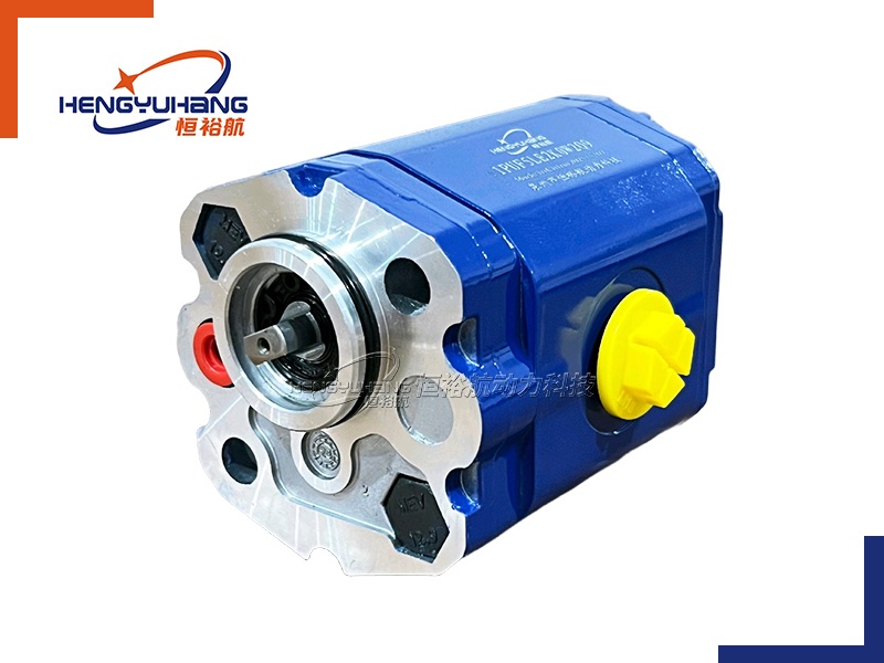
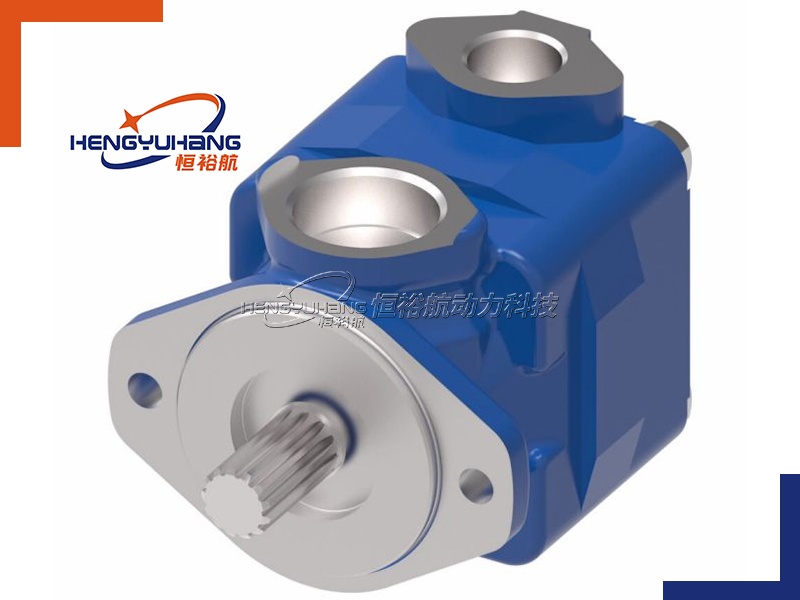
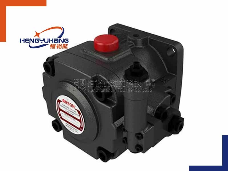
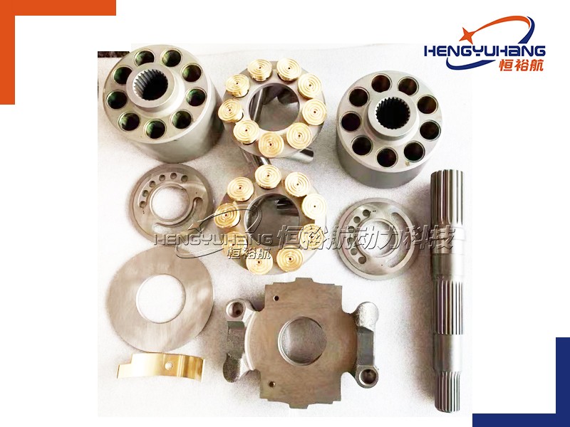
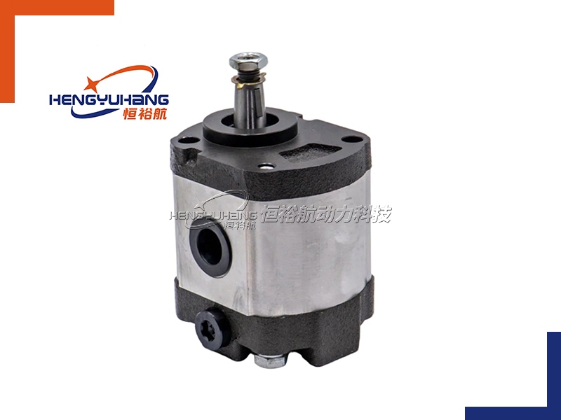
1.1 Key Components of a Gear Pump
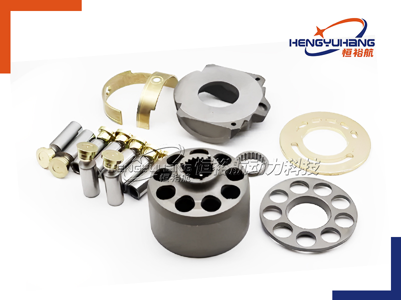
Before diving into the working process, it’s important to understand the core components that enable a gear pump to function:
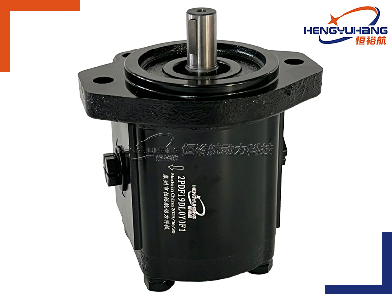
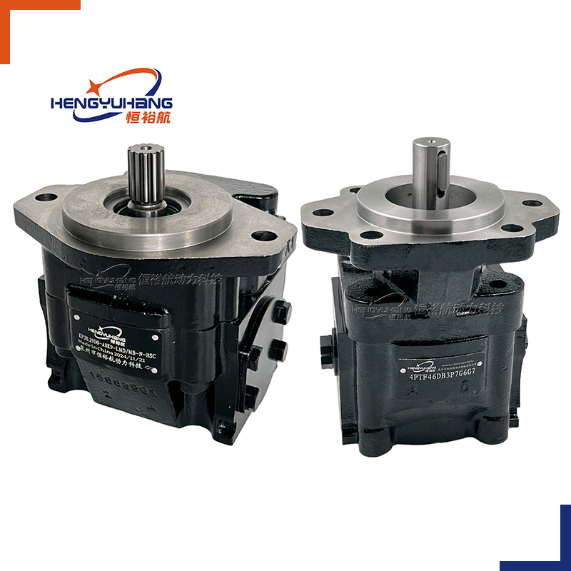
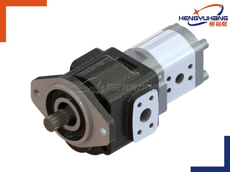
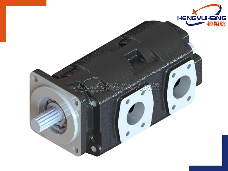
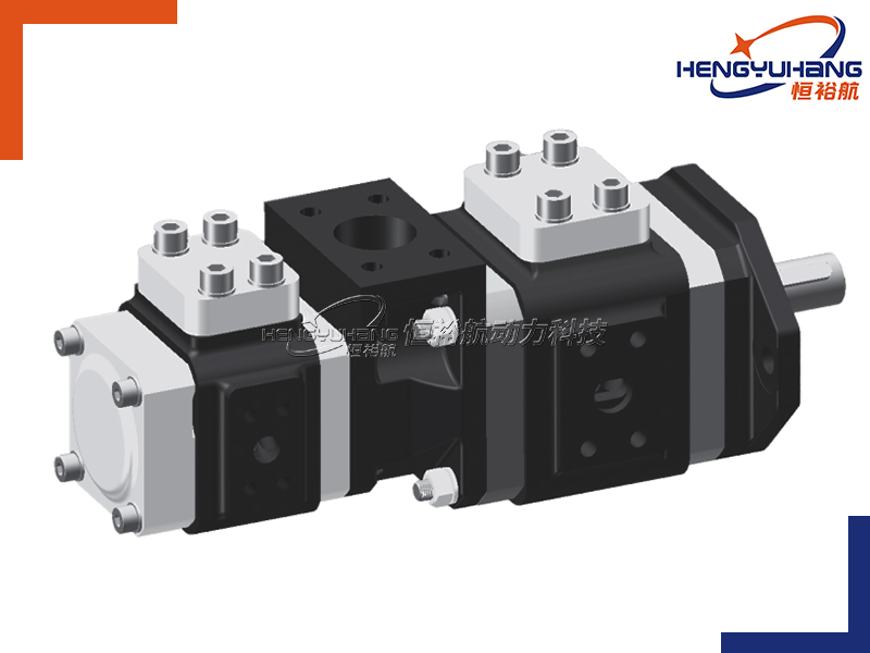
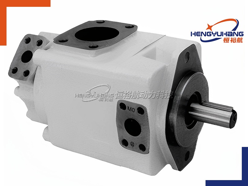
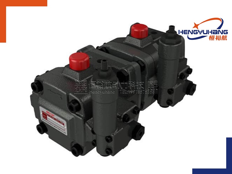
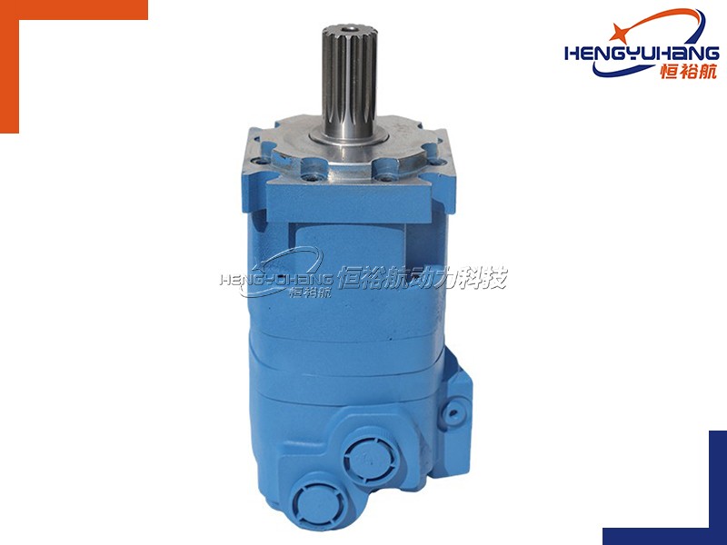
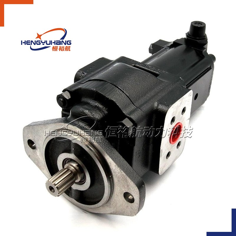
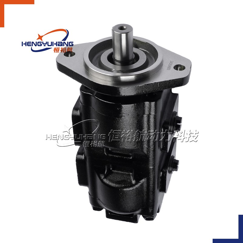
Driving Gear: Connected to the motor or power source, it rotates and drives the driven gear.
Driven Gear: Meshes with the driving gear and rotates in the opposite direction.
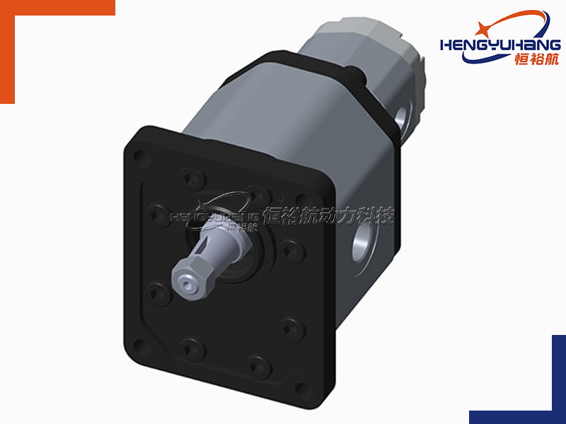
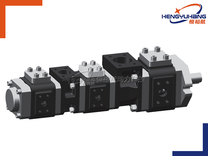
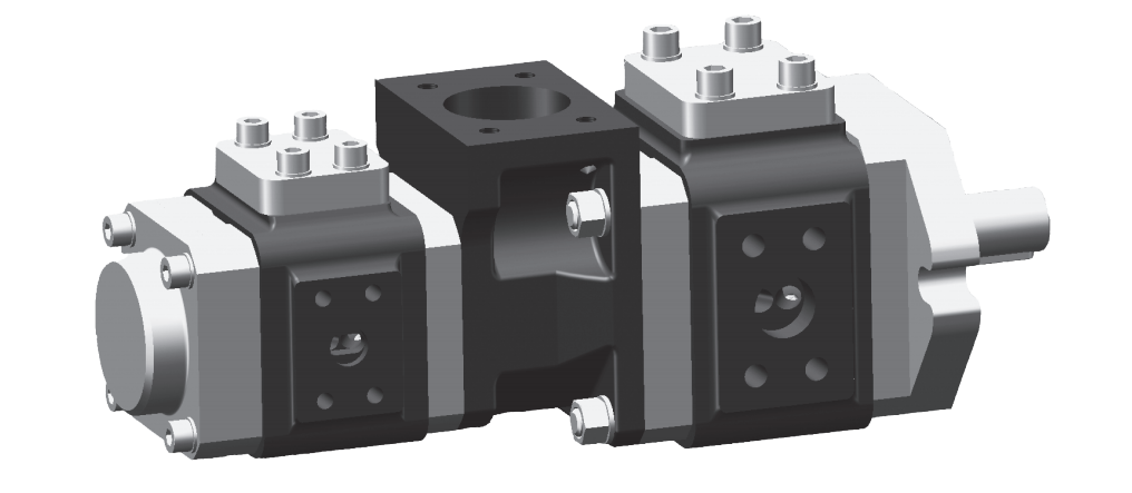
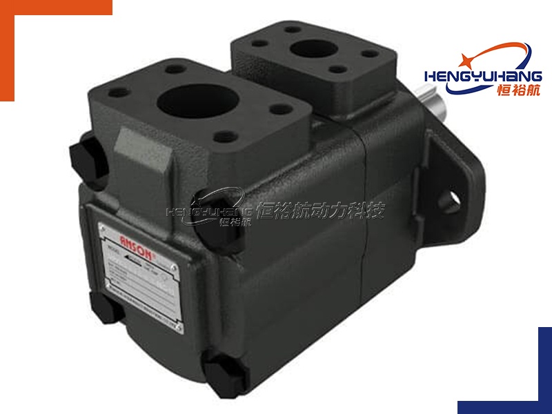
Pump Casing: Encloses the two gears, creating a sealed chamber where fluid is trapped and moved.
Inlet Port: Where fluid enters the pump as the gears separate.
Discharge Port: Where fluid exits the pump as the gears mesh together.
Shaft Seals: Prevent fluid leakage around the drive shaft.
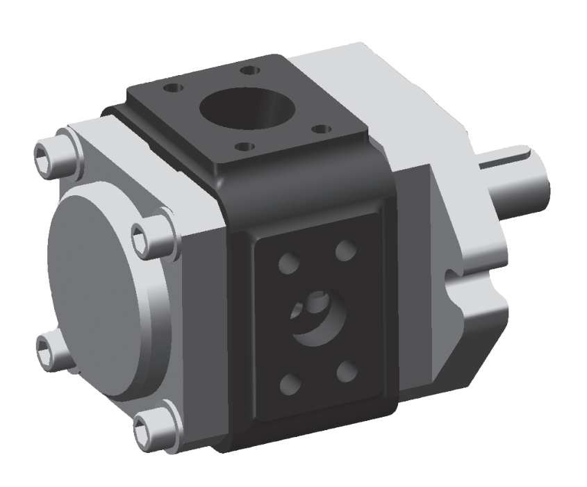
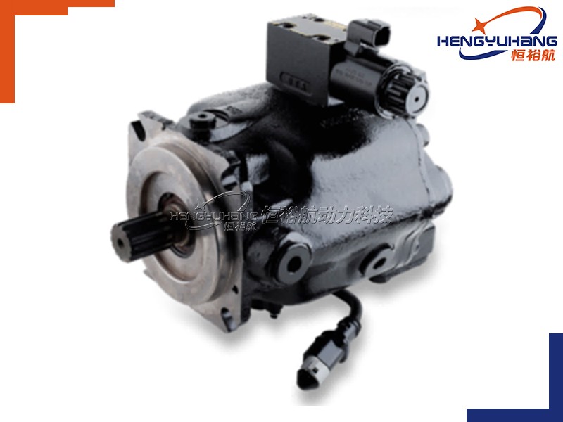
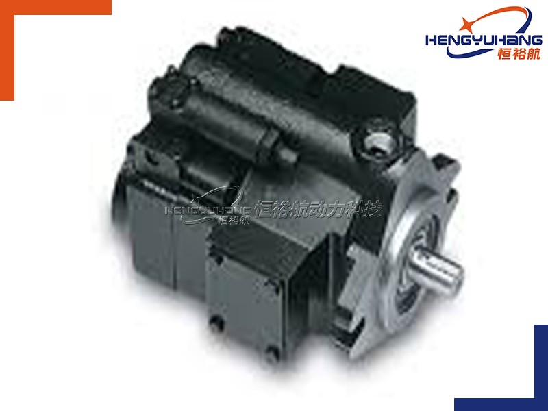
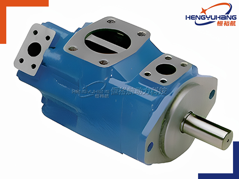
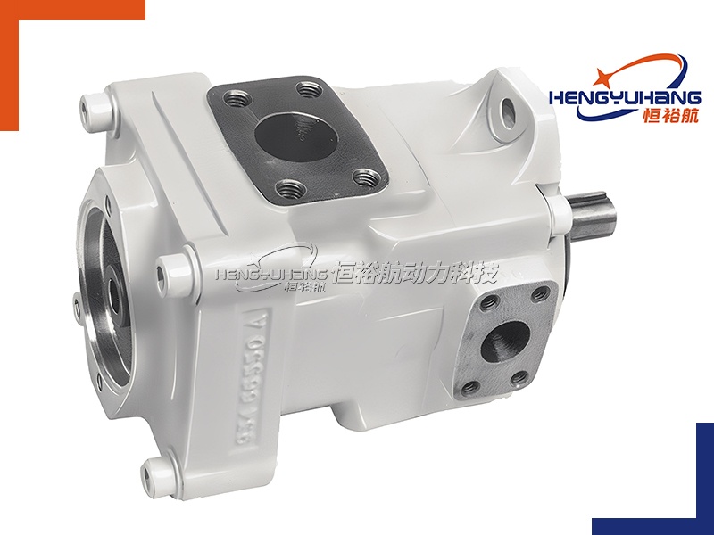
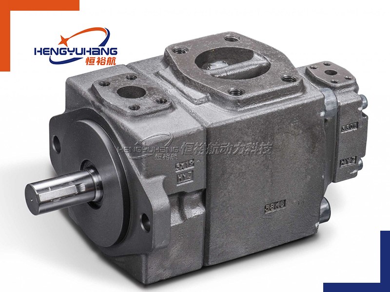
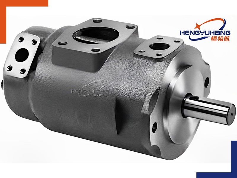
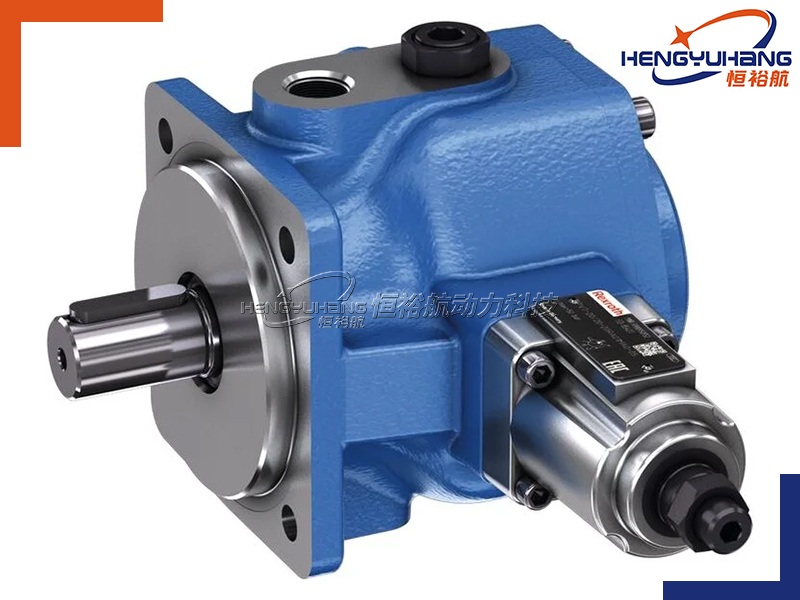
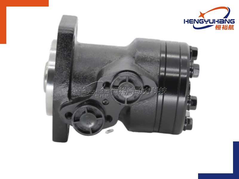
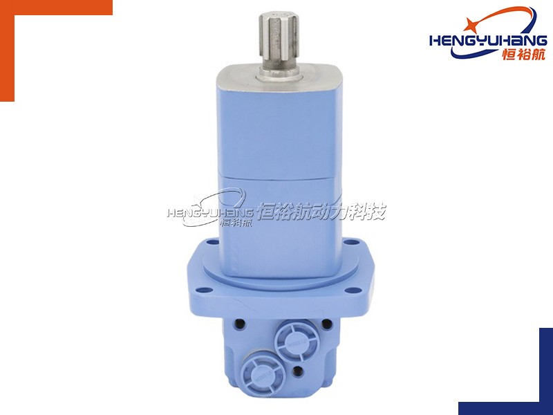
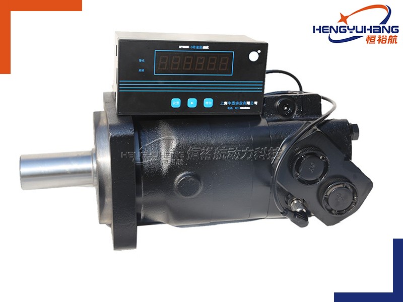
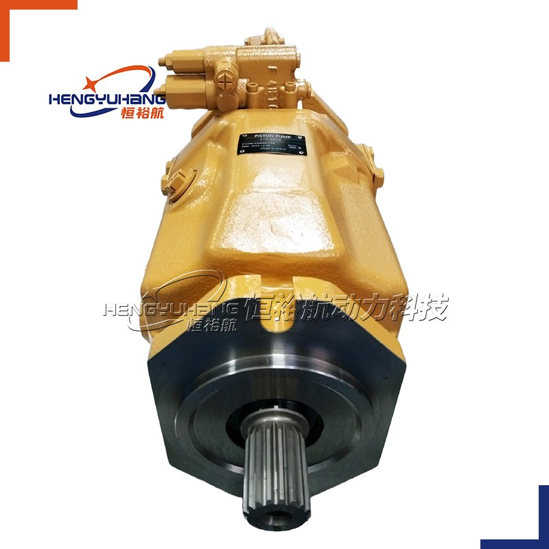
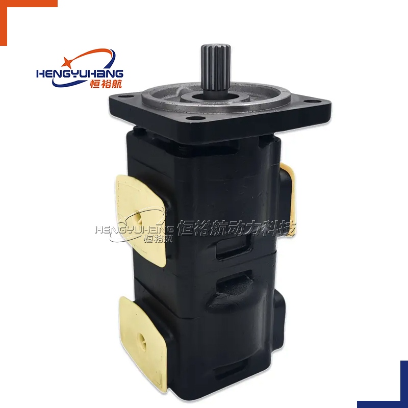
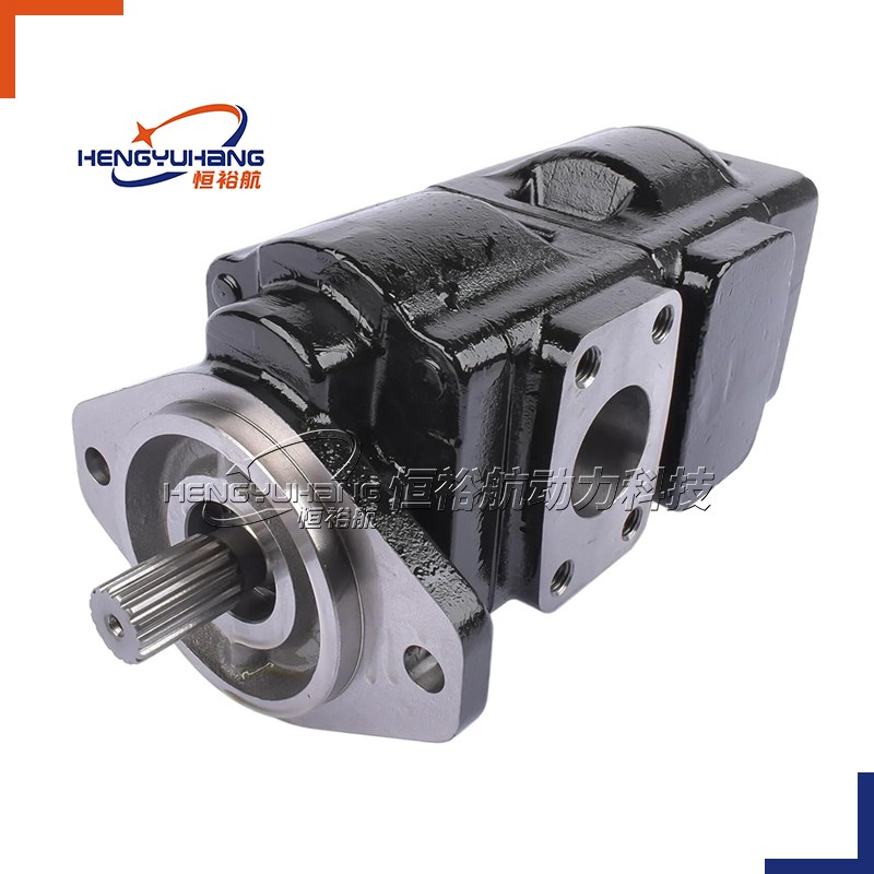
Image 1: Cross-sectional view of a gear pump, showing the driving gear, driven gear, inlet port, discharge port, and pump casing. (Optimize image alt text: "Cross-section of a gear pump showing key components - driving gear, driven gear, inlet, discharge")
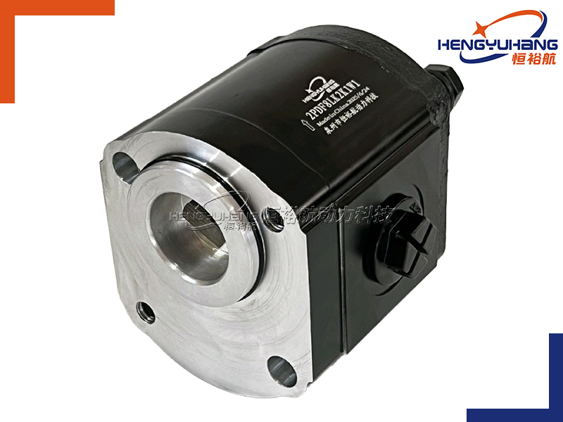
1.2 Step-by-Step Working Process
The operation of a gear pump can be divided into three key stages, all happening simultaneously as the gears rotate:
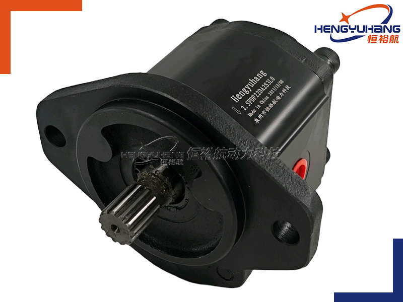
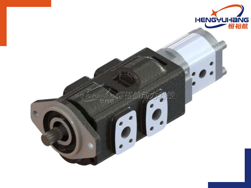
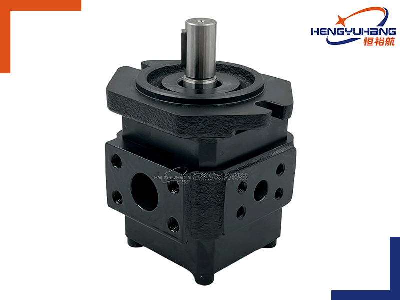
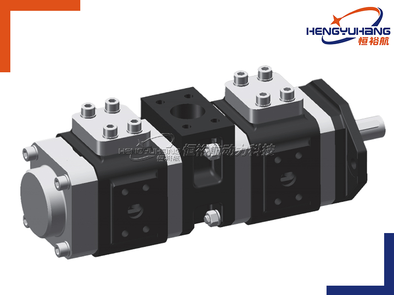
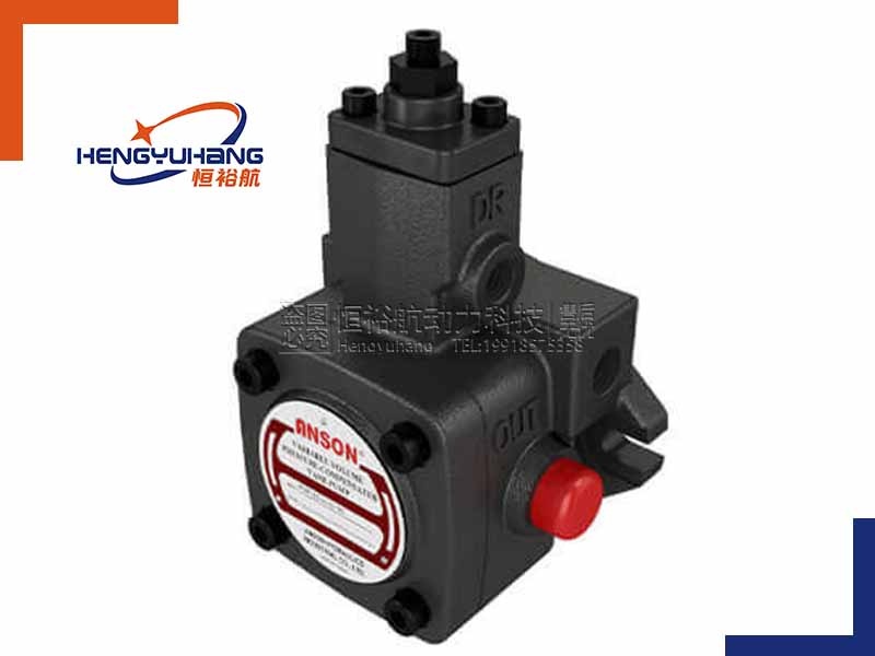
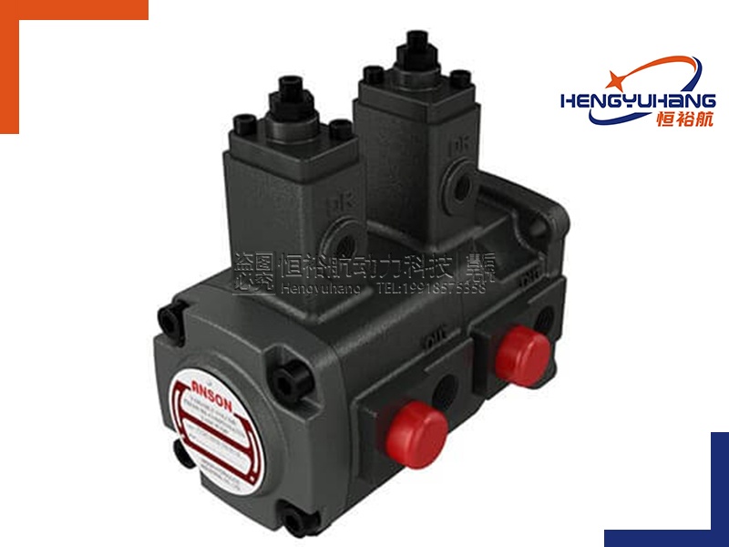
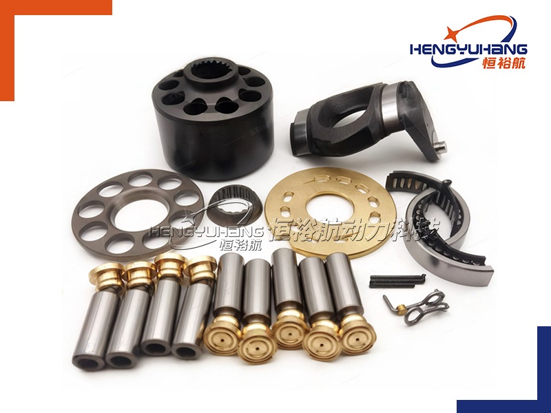
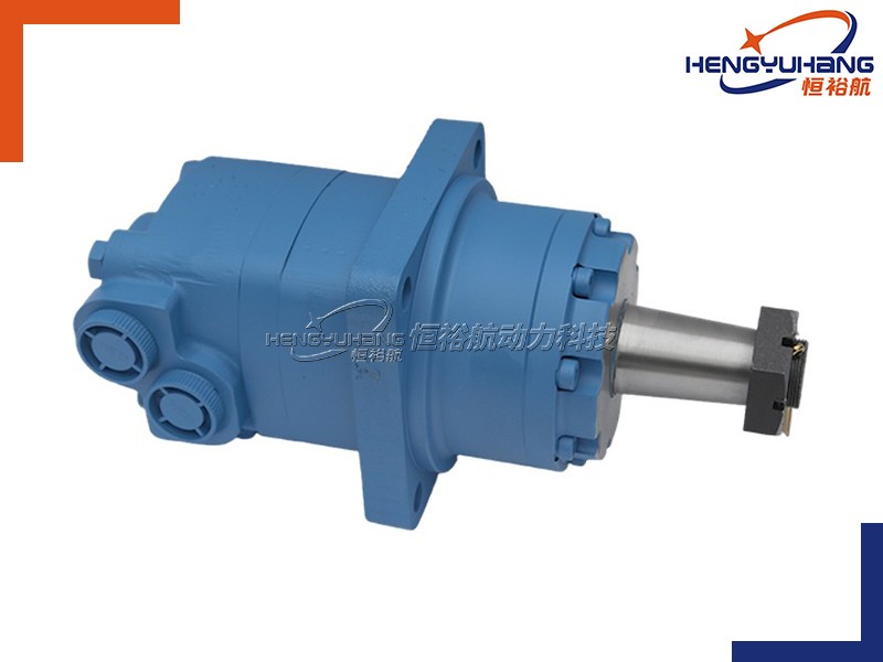
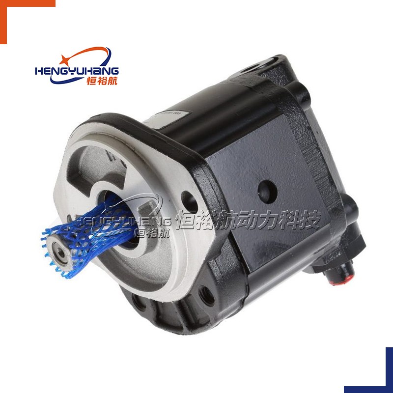
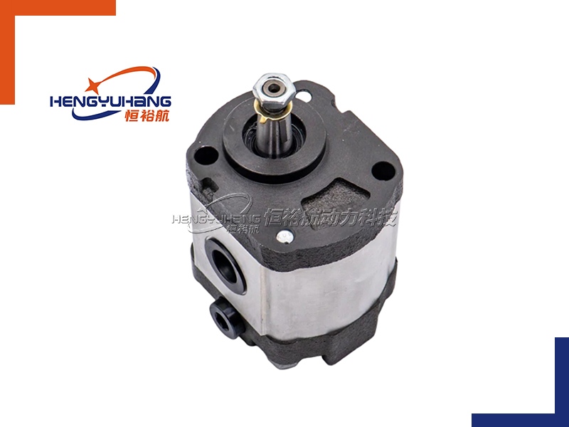
Suction Stage: As the driving gear (powered by a motor) rotates, it pulls the driven gear in the opposite direction. The meshing teeth of the two gears separate at the inlet port, creating a low-pressure zone. Atmospheric pressure pushes the fluid from the reservoir into the pump through the inlet port, filling the gaps between the gear teeth and the pump casing.
Fluid Transfer Stage: The rotating gears trap the fluid in the spaces between their teeth and carry it around the inner wall of the pump casing. Since the pump casing is sealed, the fluid cannot flow back to the inlet—instead, it is forced to move along the path created by the gear teeth and casing.
Discharge Stage: When the meshing teeth meet again at the discharge port, they squeeze the fluid trapped between them. This squeezing action creates high pressure, forcing the fluid out of the discharge port and into the hydraulic system or pipeline. The cycle repeats continuously as the gears rotate, delivering a steady flow of fluid.
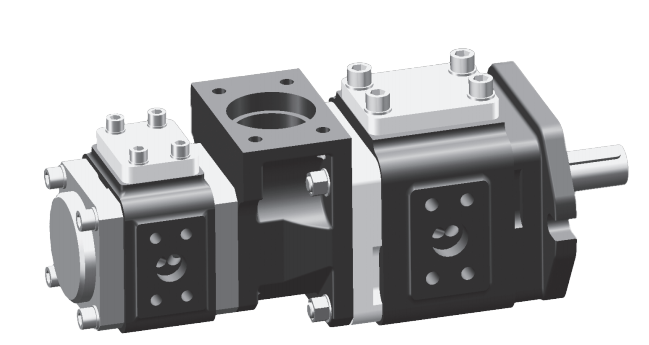
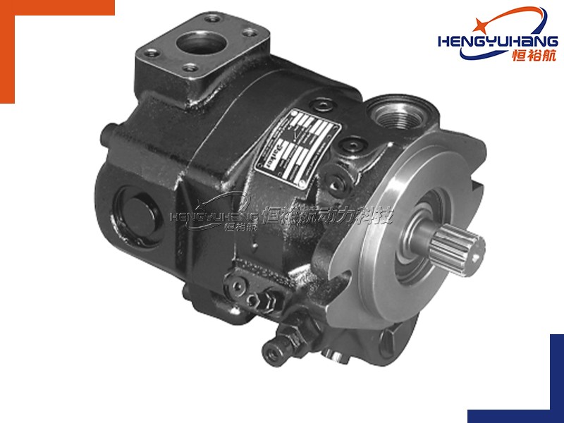
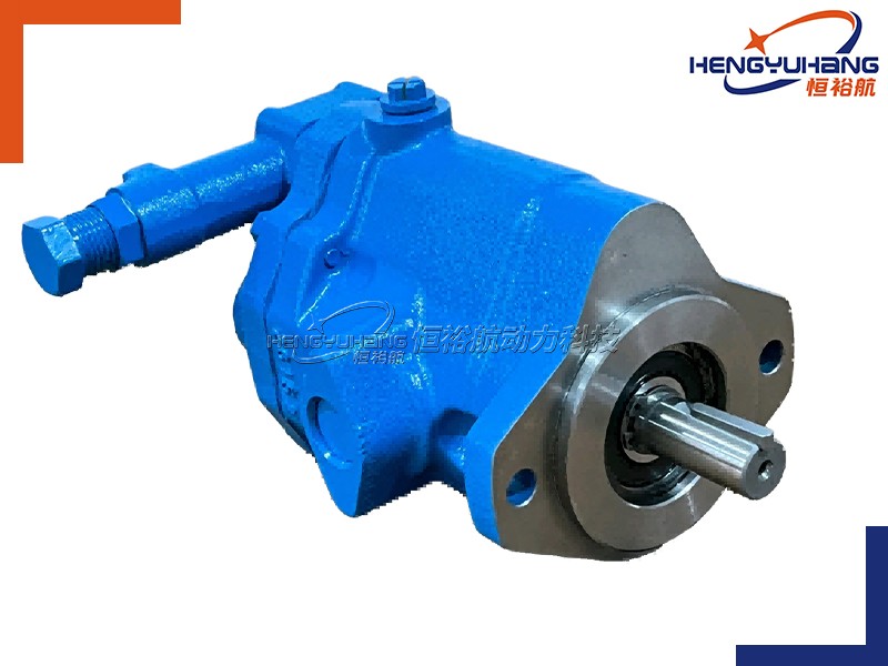
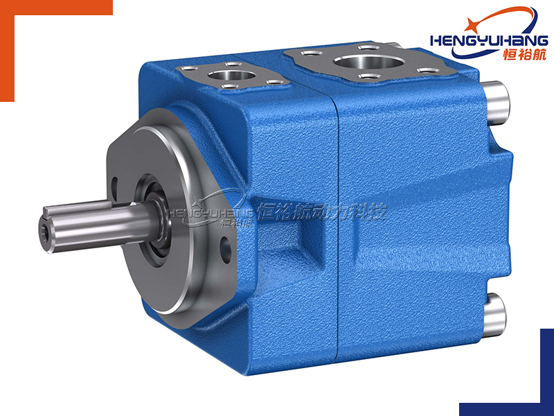
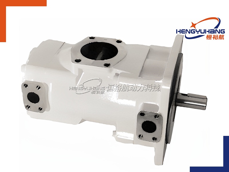
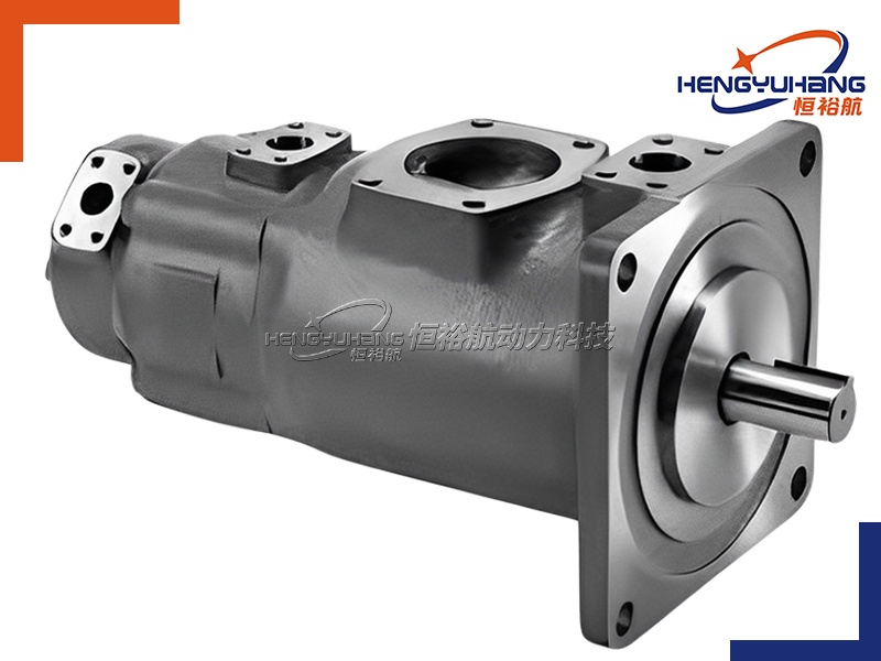
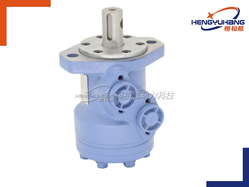
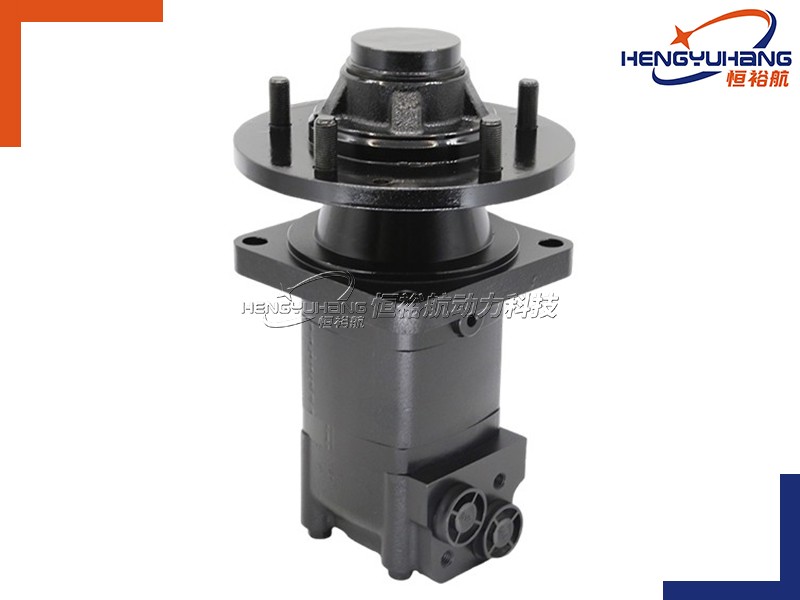
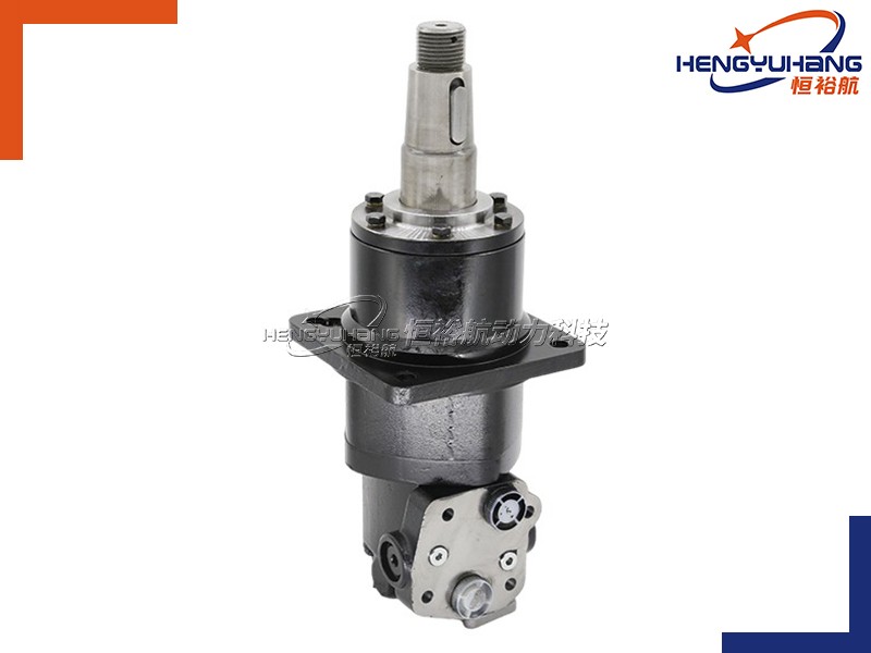
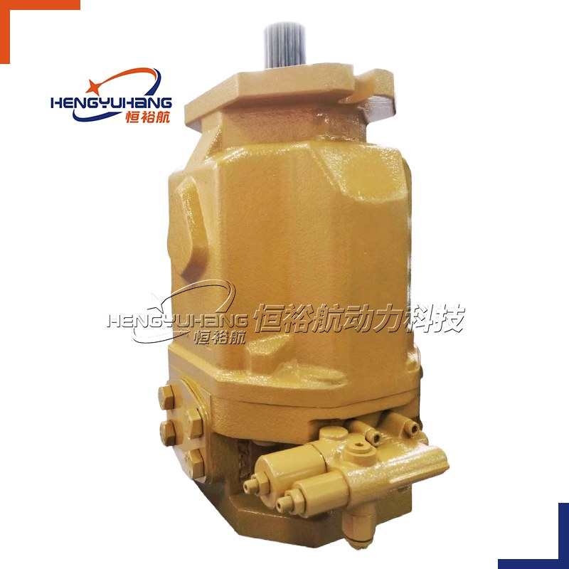
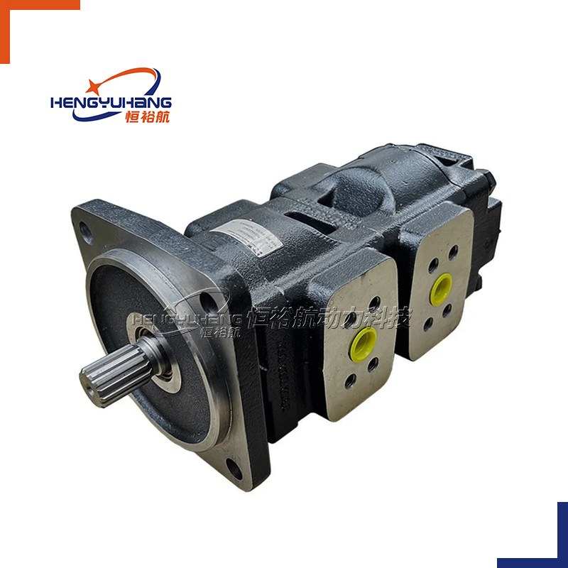
Image 2: Animated diagram showing the three stages of a gear pump’s operation (suction, transfer, discharge). (Optimize image alt text: "Gear pump working principle - suction, fluid transfer, discharge stages animation")
Key Takeaway: Gear pumps work by using meshing gears to create pressure differentials, pulling fluid in and pushing it out—delivering a consistent, fixed flow rate. This simplicity makes them durable and easy to maintain, but proper installation and operation are critical to avoid premature failure.
2. Critical Installation Precautions for Gear Pumps
Incorrect installation is one of the most common causes of gear pump failure, reduced efficiency, and fluid leakage. Follow these key precautions to ensure your gear pump operates reliably and has a long service life. All tips are optimized for practicality and aligned with industry best practices, making them valuable for both professionals and DIY enthusiasts.
2.1 Pre-Installation Preparation
Inspect the Pump and Components: Before installation, check the gear pump for any damage (e.g., cracked casing, bent shafts, or worn teeth) during shipping. Also, inspect the inlet and discharge ports for debris, and ensure all seals are intact and properly seated. Replace any damaged parts before proceeding.
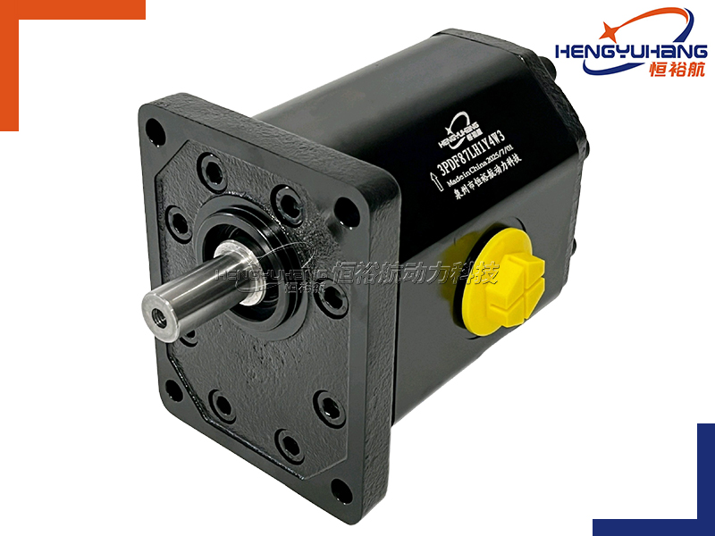
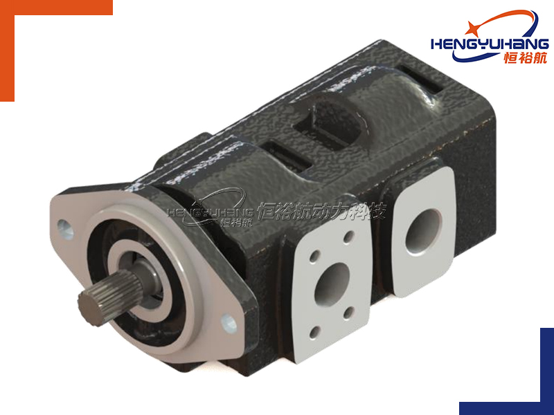
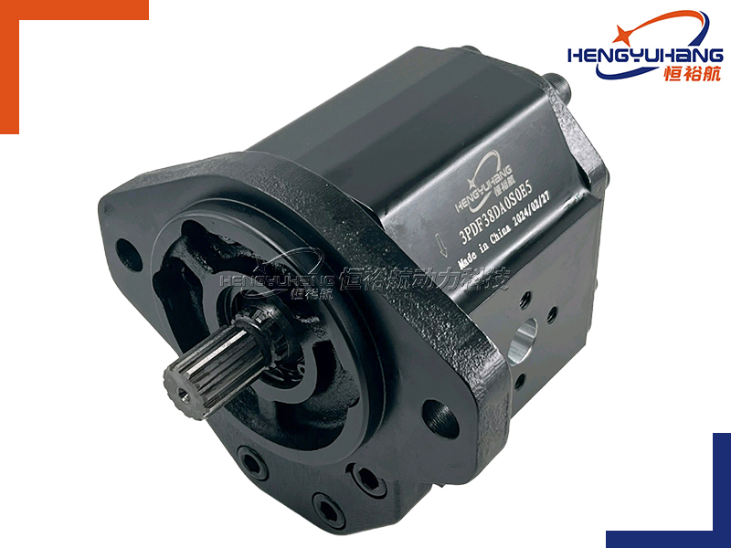
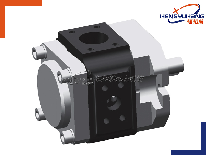
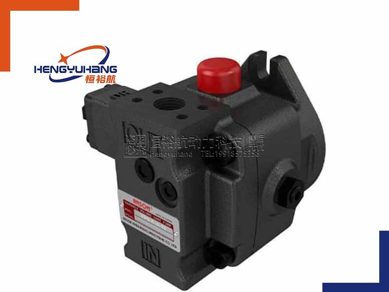
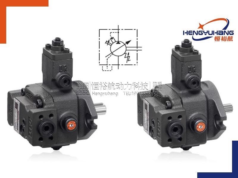
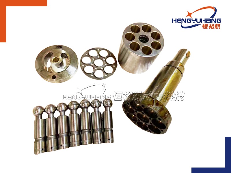
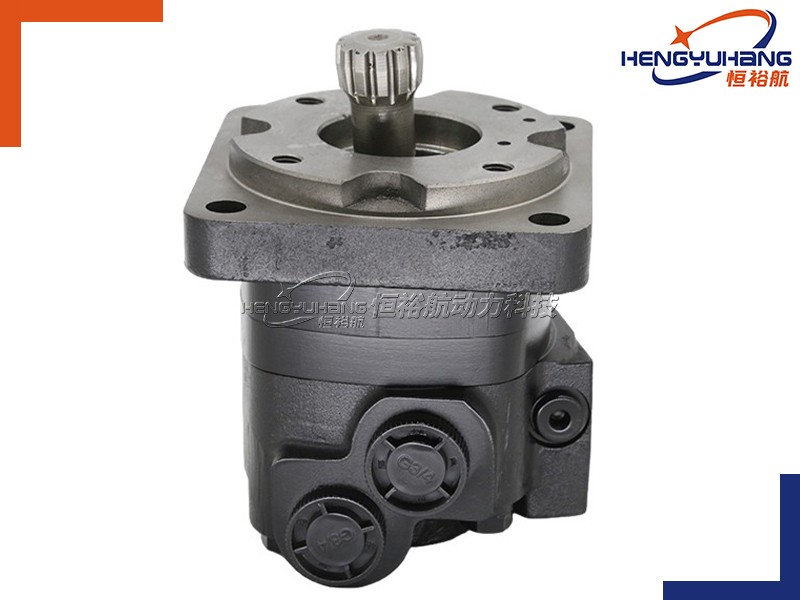
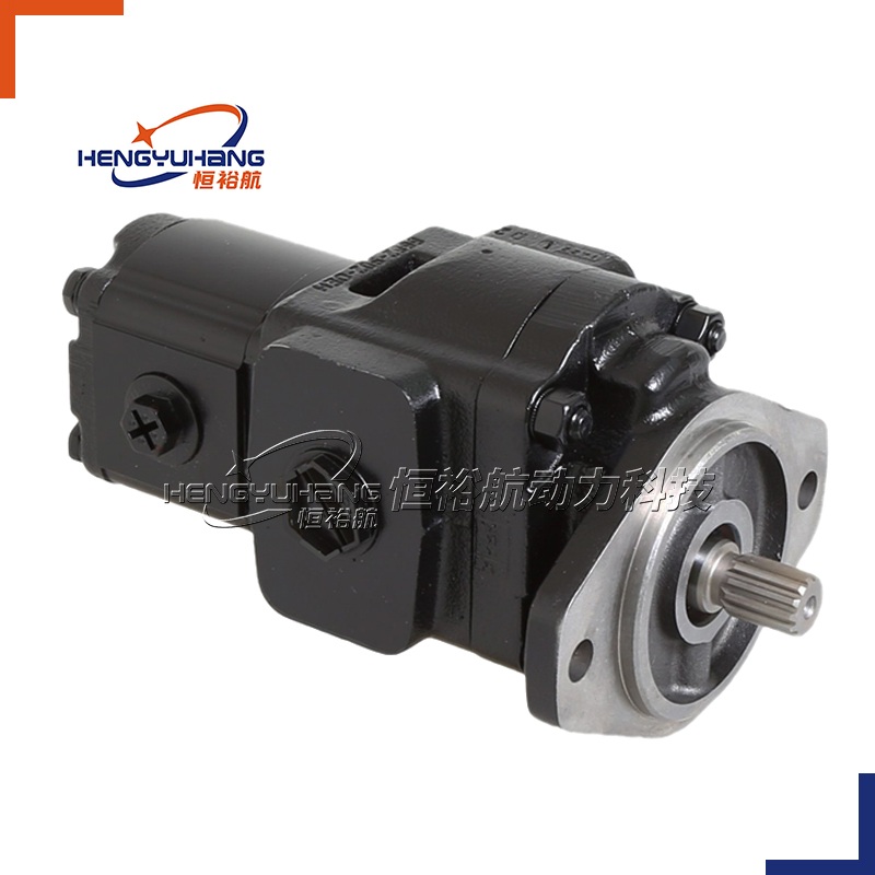
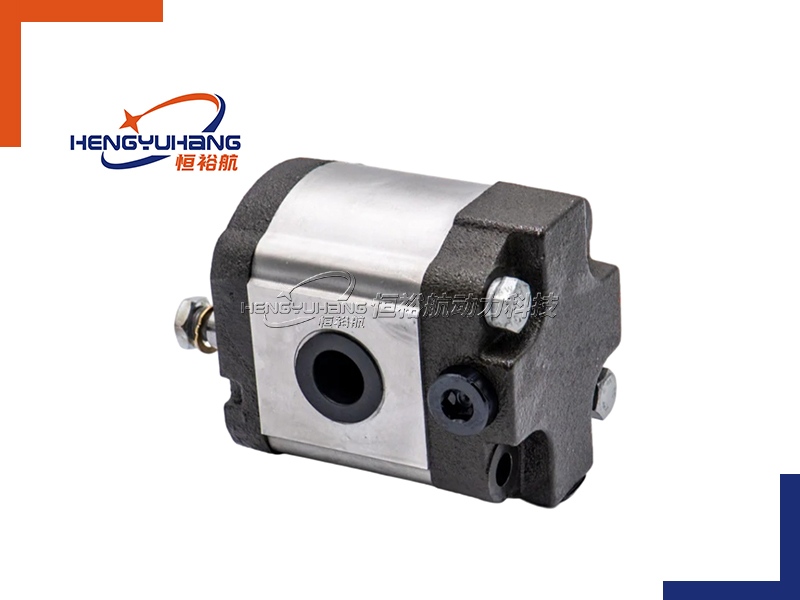
Choose the Right Mounting Location: Install the gear pump in a dry, well-ventilated area away from high temperatures, direct sunlight, and corrosive substances. Ensure there is enough space around the pump for maintenance (e.g., accessing seals, gears, or the motor). Avoid mounting the pump in a location where it will be exposed to excessive vibration, which can damage the gears and bearings.
Check Fluid Compatibility: Ensure the fluid being pumped is compatible with the pump’s materials (e.g., cast iron, stainless steel) and seals. Using incompatible fluids can cause seal degradation, corrosion, and gear wear. Refer to the pump manufacturer’s specifications for recommended fluid types and viscosity ranges.
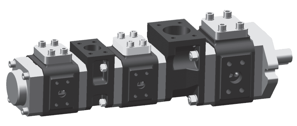
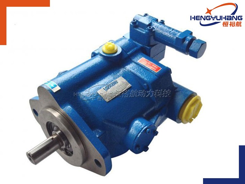
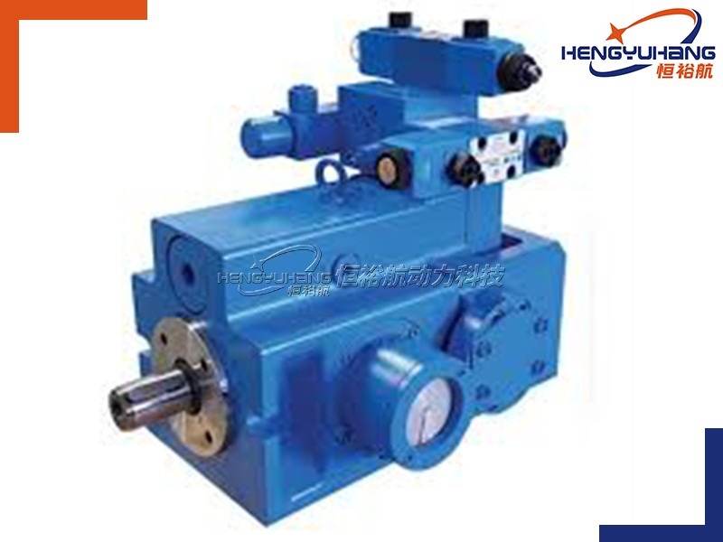
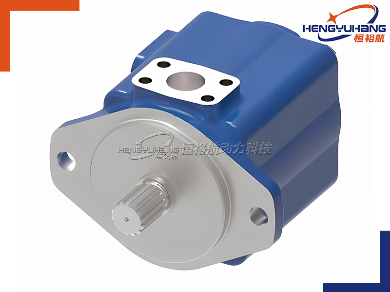
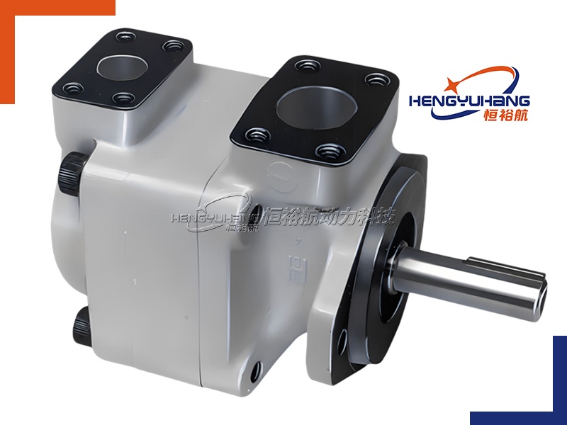
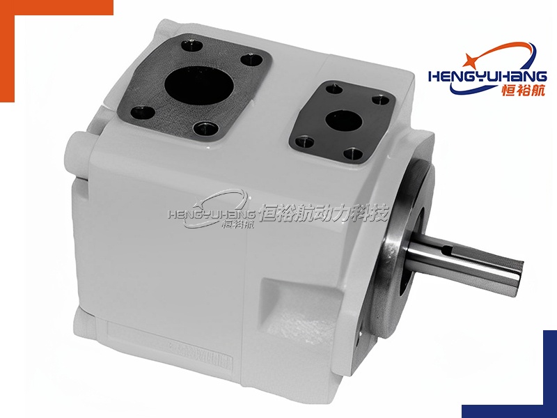
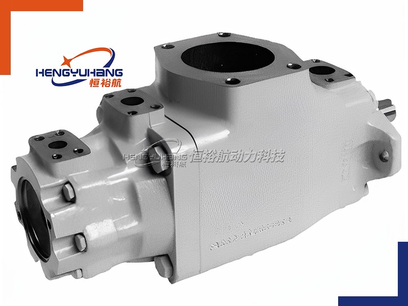
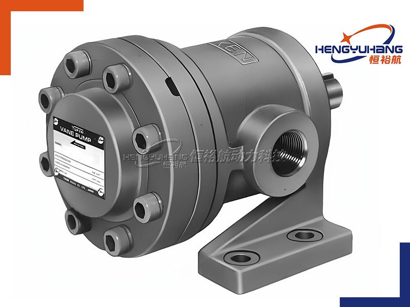
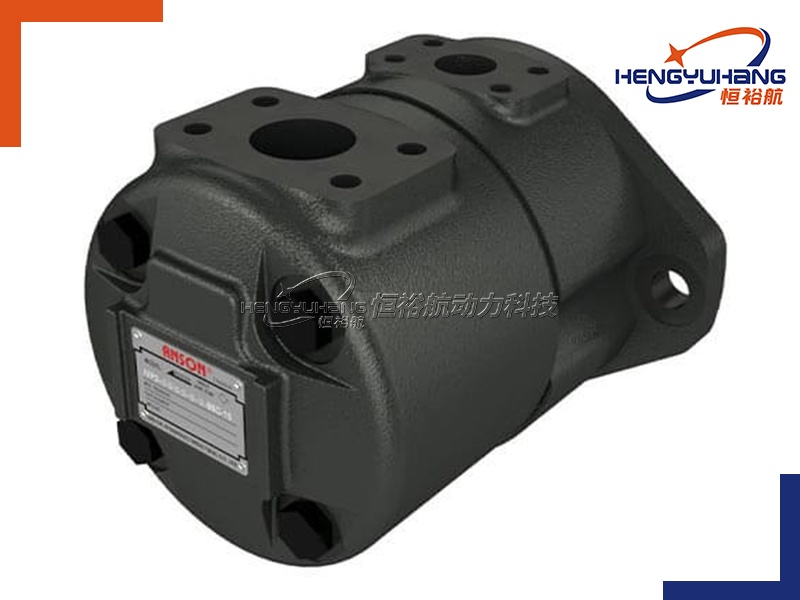
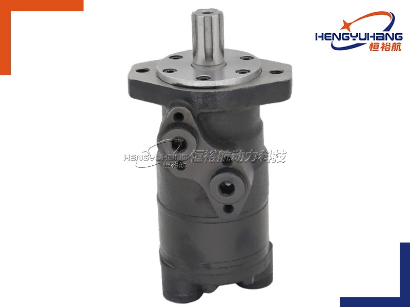
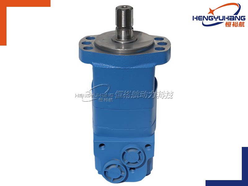
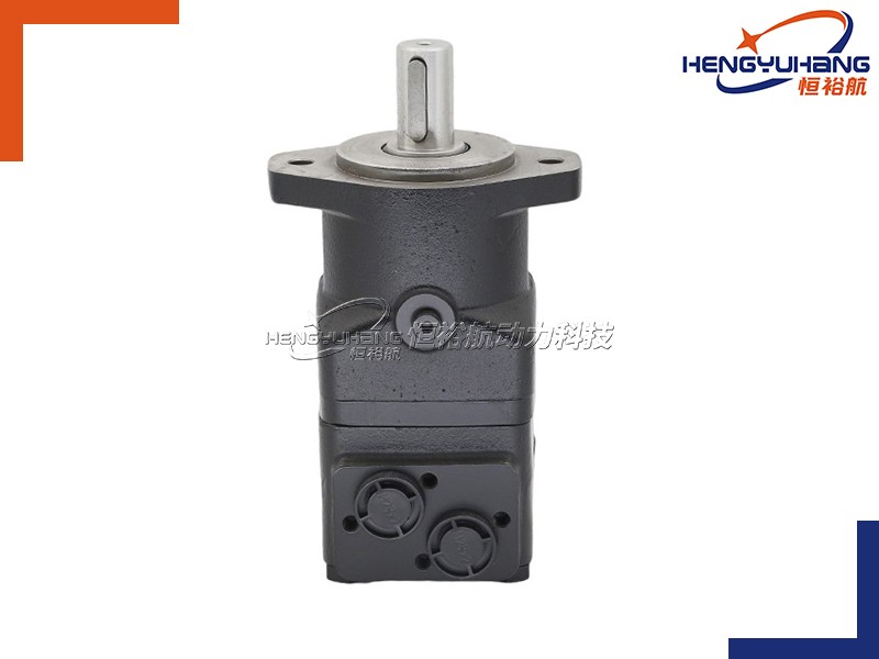
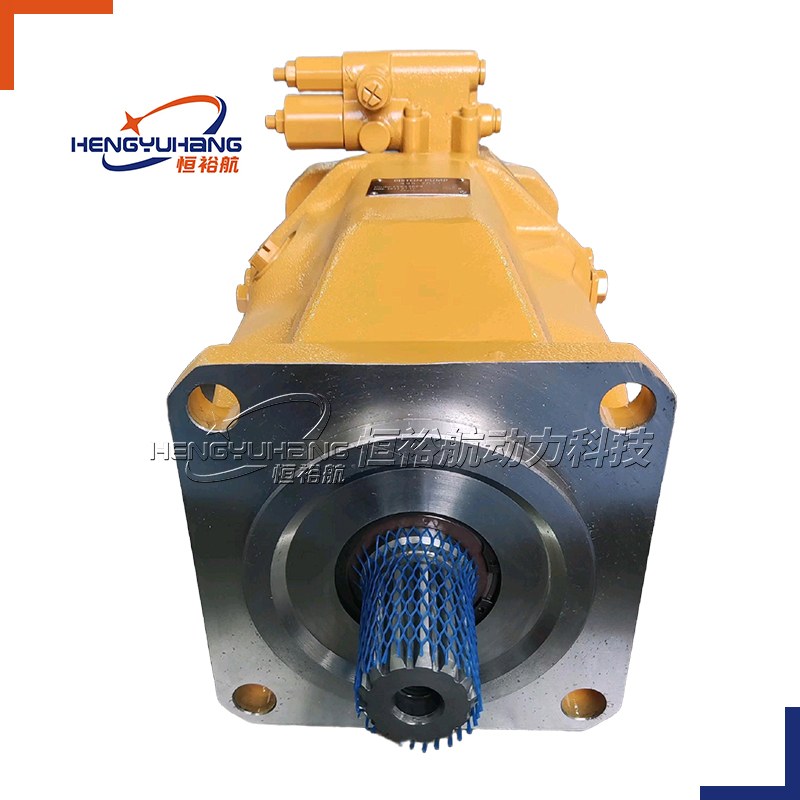
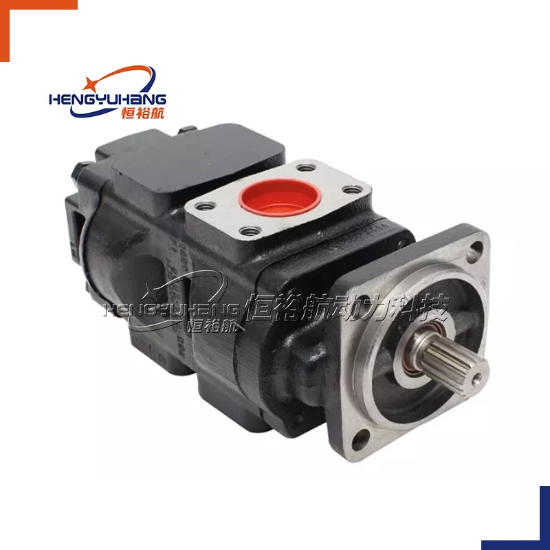
Image 3: Proper gear pump mounting location with adequate space for maintenance. (Optimize image alt text: "Gear pump proper mounting location with ventilation and maintenance space")
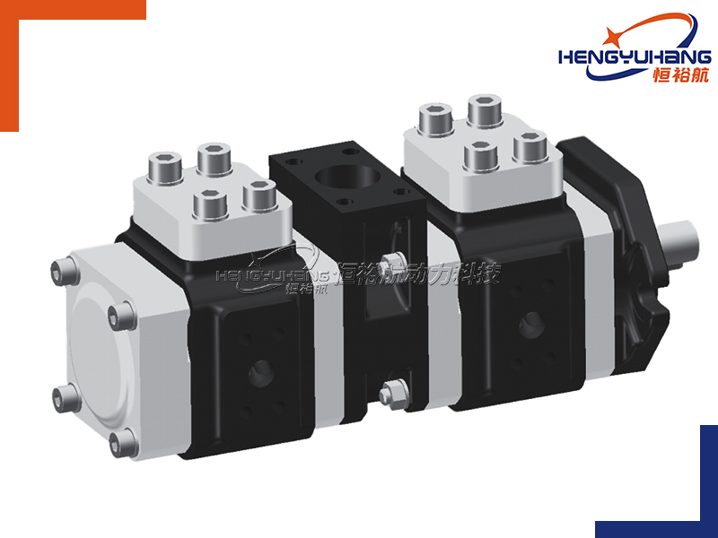
2.2 Installation Steps & Precautions
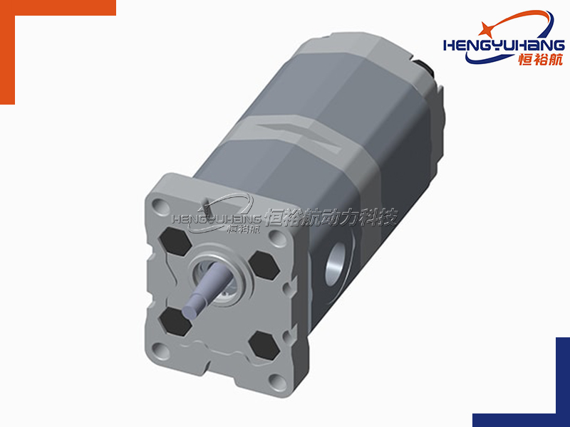
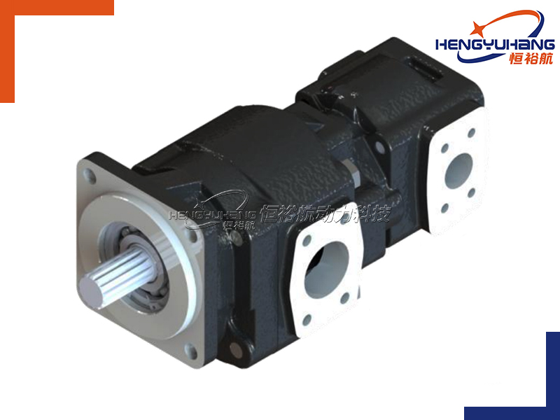
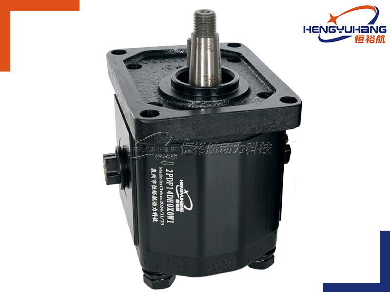
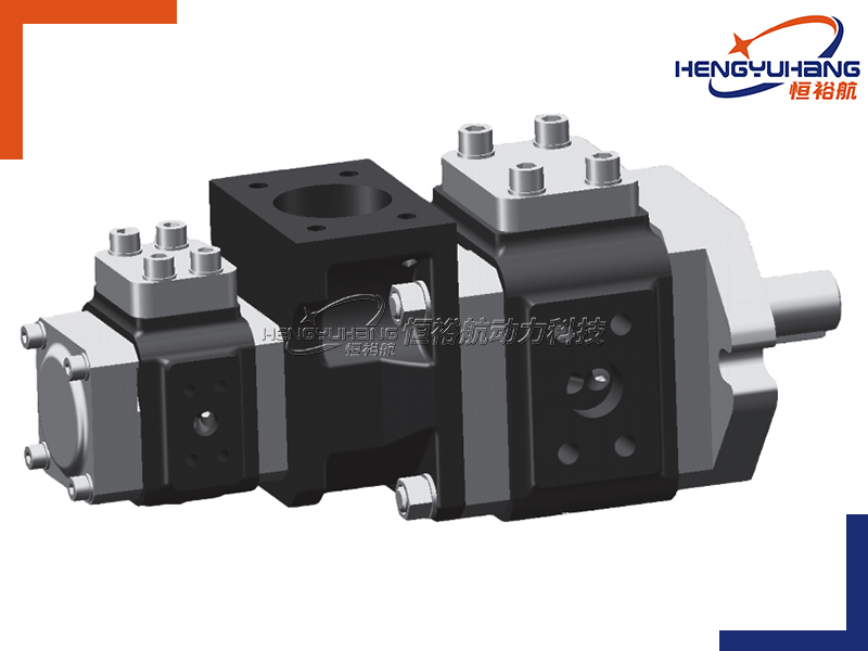
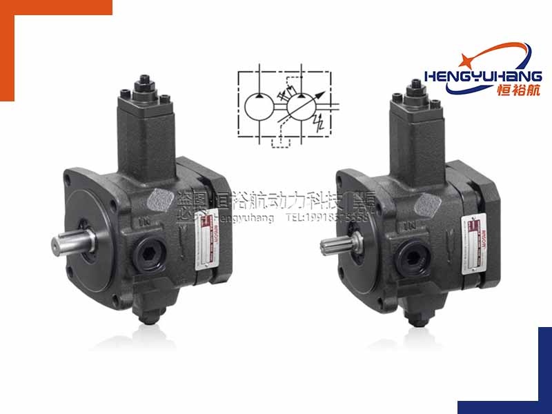
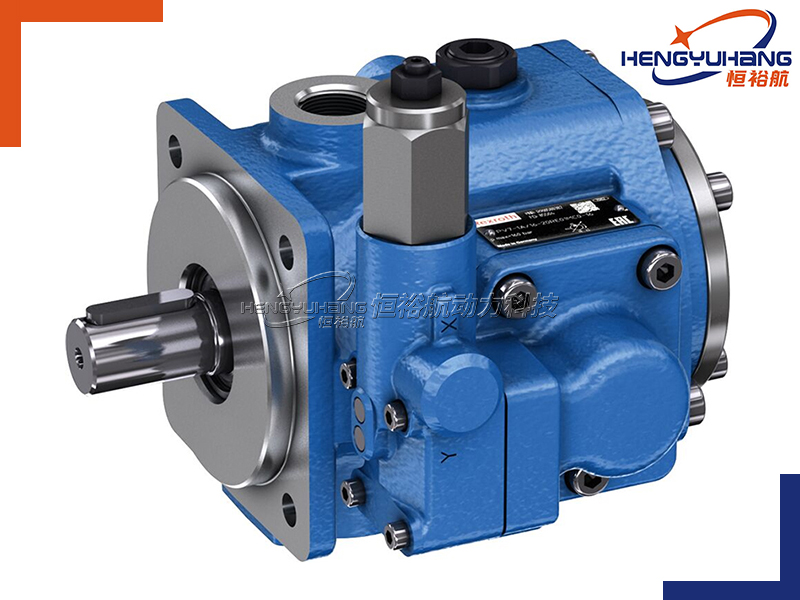
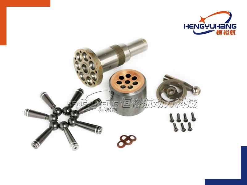
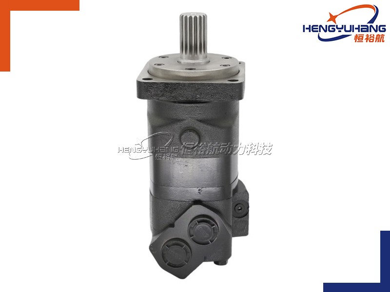
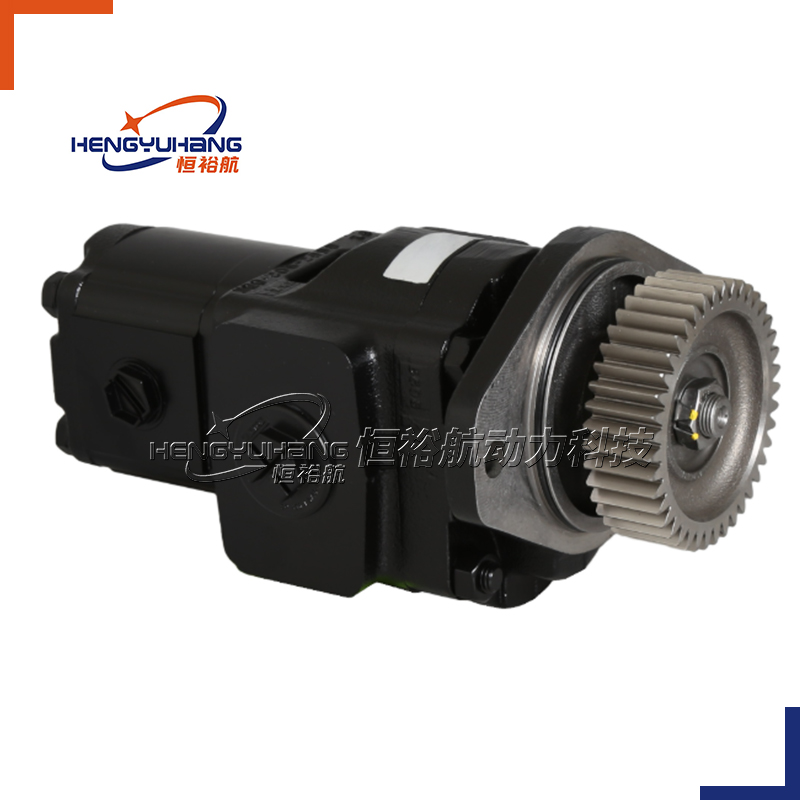
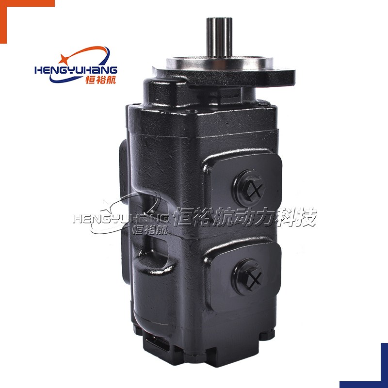
Align the Pump and Motor: Misalignment between the gear pump and the motor is a major cause of shaft wear, seal leakage, and noise. Ensure the pump shaft and motor shaft are perfectly aligned (both radially and axially). Use a straightedge or alignment tool to check alignment, and adjust the motor mount if necessary. Avoid over-tightening coupling bolts, as this can distort the alignment.
Secure the Pump Firmly: Use high-quality bolts to mount the pump to a stable base. The base should be rigid enough to absorb vibration and prevent movement during operation. Tighten the bolts evenly to ensure the pump is level and secure—loose mounting can cause excessive vibration and damage internal components.
Install Inlet and Discharge Pipes Correctly:
Use pipes that are the same size as the pump’s inlet and discharge ports (or larger, to reduce flow resistance).
Install a strainer at the inlet port to prevent debris from entering the pump and damaging the gears. The strainer should have a mesh size appropriate for the fluid and pump specifications.
Use flexible hoses or couplings between the pump and pipes to absorb vibration and compensate for minor misalignment. Avoid sharp bends in the inlet pipe, as this can restrict fluid flow and create suction issues.
Ensure all pipe connections are tight and leak-proof. Use thread sealant or gaskets where necessary, and avoid over-tightening threads, which can damage the ports.
Prime the Pump Before Operation: Most gear pumps require priming (filling the pump with fluid) before starting. Failure to prime the pump can cause dry running, which damages the gears, seals, and bearings. Fill the pump through the discharge port until fluid overflows, then close the discharge valve temporarily before starting the motor.
Check Rotation Direction: Ensure the pump’s rotation direction matches the motor’s rotation direction. The correct rotation direction is usually marked on the pump casing. Reverse rotation can cause the pump to not deliver fluid, damage the gears, or create excessive pressure.
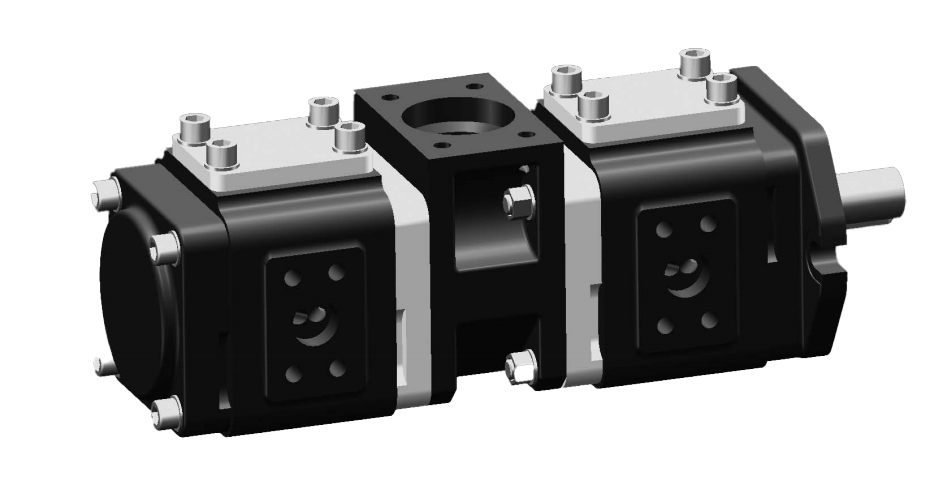
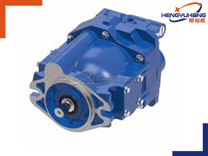
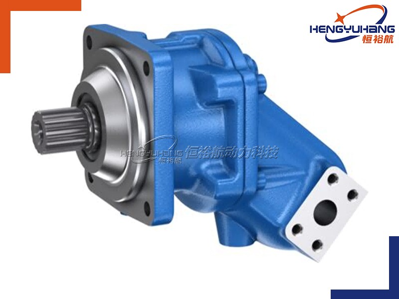
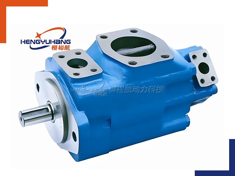
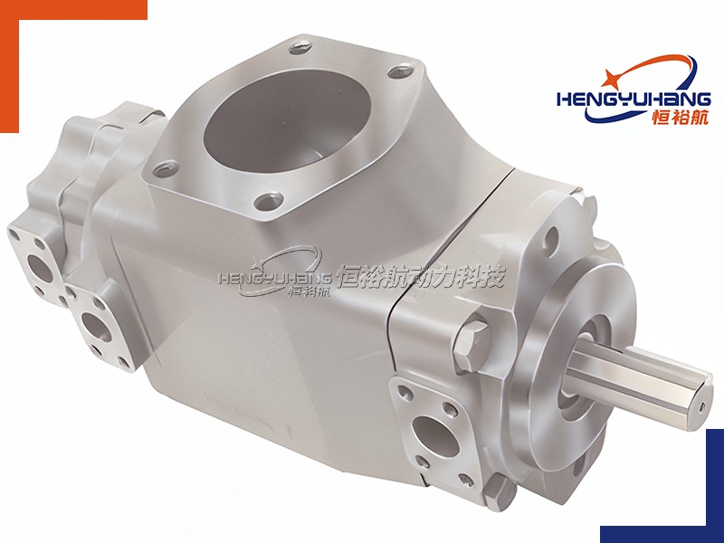
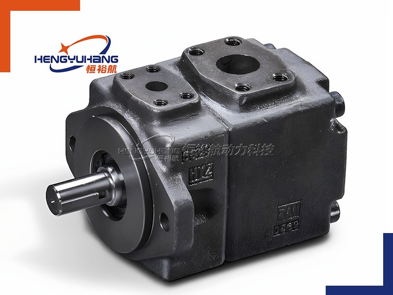
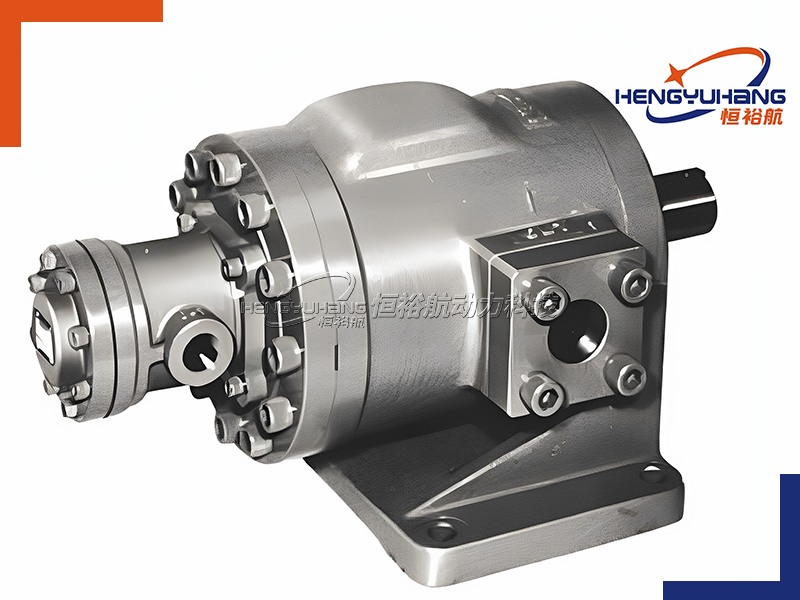
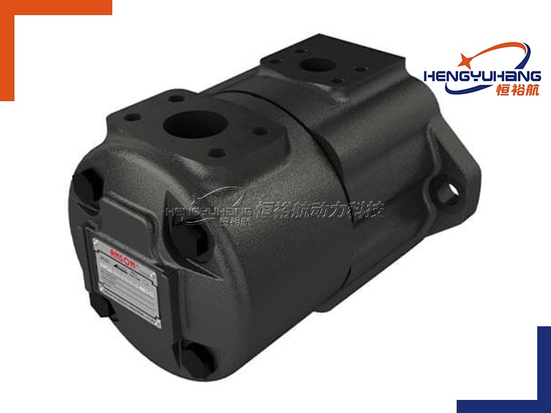
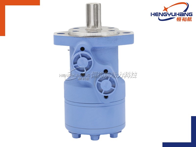
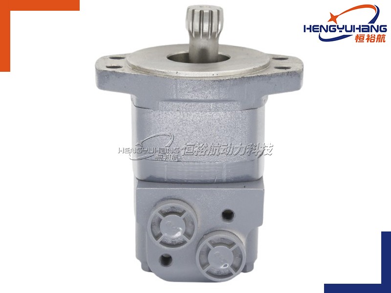
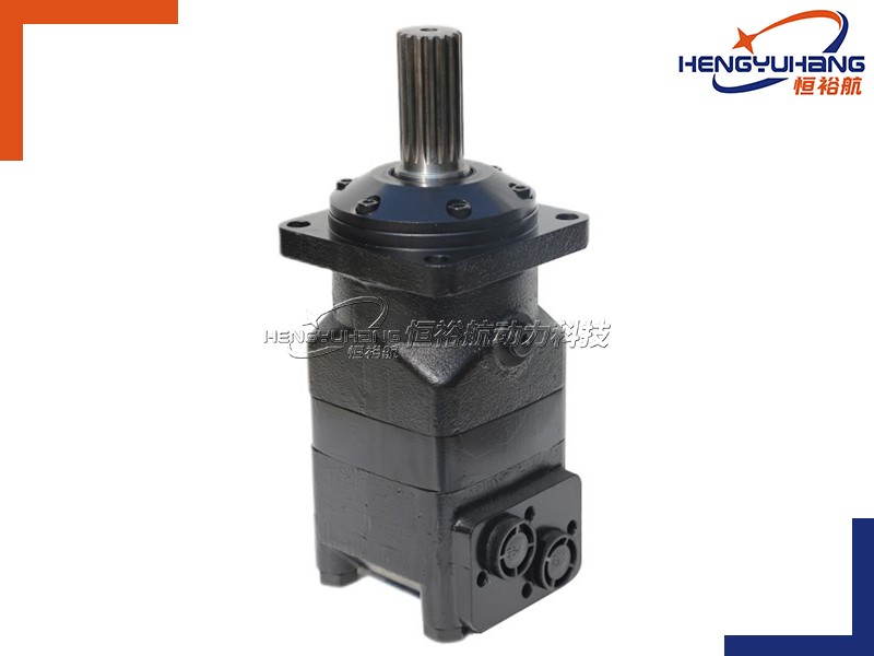
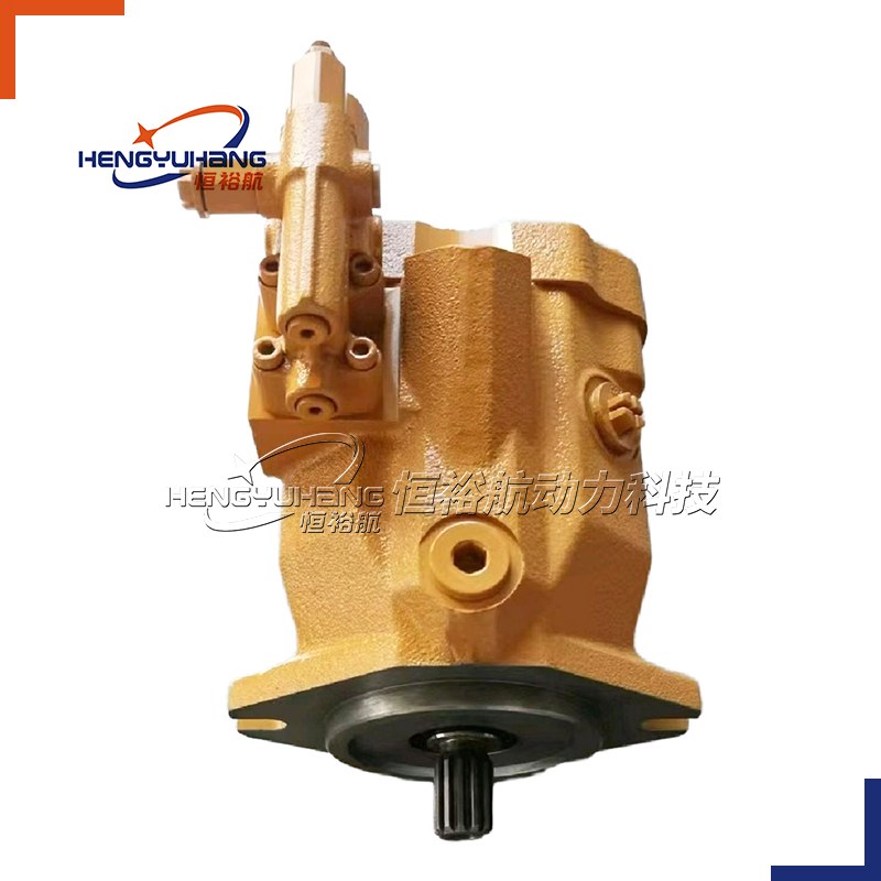
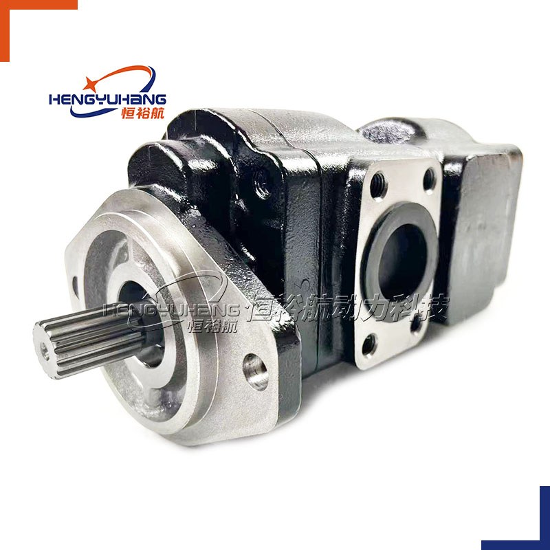
Image 4: Correct alignment of gear pump and motor with flexible coupling. (Optimize image alt text: "Gear pump and motor alignment with flexible coupling to prevent misalignment")
2.3 Post-Installation Checks
After installation, perform a test run to ensure the pump is operating correctly:Start the motor at low speed and check for unusual noise, vibration, or leakage.Monitor the pump’s pressure and flow rate to ensure they match the system requirements.Check the temperature of the pump and fluid—excessive heat may indicate misalignment, insufficient lubrication, or a blockage.Shut down the pump and inspect all connections for leaks. Tighten any loose fittings and address any issues before regular operation.
3. Gear Pump Fault Diagnosis: Common Issues & Solutions
Even with proper installation, gear pumps may experience issues over time. Being able to quickly identify and resolve faults can minimize downtime and reduce repair costs. Below are the most common gear pump faults, their causes, and step-by-step solutions—presented in a clear, easy-to-follow format for quick reference.
3.1 No Fluid Flow or Low Flow Rate
Symptoms: The pump runs but delivers little to no fluid; flow rate is significantly lower than expected.
Causes & Solutions: Air in the Pump (Cavitation): Air enters the pump through loose inlet connections, a damaged suction line, or insufficient fluid in the reservoir. Solution: Check the inlet line for leaks, ensure the reservoir is filled to the correct level, and bleed air from the pump by opening the discharge valve until fluid flows without bubbles.Clogged Inlet Strainer or Pipe: Debris blocks the inlet, restricting fluid flow. Solution: Remove and clean the inlet strainer; inspect the inlet pipe for blockages and clear them if necessary.Reverse Rotation: The pump is rotating in the wrong direction. Solution: Check the rotation direction (marked on the pump casing) and adjust the motor wiring to correct it.Worn or Damaged Gears: Over time, gear teeth can wear down or become damaged, reducing the pump’s displacement. Solution: Disassemble the pump and inspect the gears; replace worn or damaged gears with genuine parts.
Image 5: Clogged inlet strainer causing low flow in a gear pump. (Optimize image alt text: "Clogged inlet strainer in gear pump - cause of low flow rate")
3.2 Excessive Noise or Vibration
Symptoms: The pump makes loud, grinding, or rattling noises; excessive vibration is felt during operation.
Causes & Solutions:Misalignment Between Pump and Motor: As mentioned earlier, misalignment causes friction and vibration. Solution: Recheck and realign the pump and motor using an alignment tool.Worn Bearings: Bearings support the pump shaft and can wear out over time, causing noise and vibration. Solution: Disassemble the pump and replace worn bearings; ensure the new bearings are properly lubricated.Air in the Pump (Cavitation): Cavitation creates a popping or cracking noise as air bubbles collapse. Solution: Bleed air from the pump and check for inlet leaks (see Section 3.1).Loose Mounting or Coupling: Loose bolts or coupling can cause vibration and noise. Solution: Tighten all mounting bolts and coupling bolts; replace any worn coupling components.
3.3 Fluid Leakage
Symptoms: Fluid leaks from the pump’s shaft seal, inlet/discharge ports, or mounting surface.
Causes & Solutions: Damaged Shaft Seal: Shaft seals wear out over time or are damaged by misalignment, excessive pressure, or incompatible fluid. Solution: Replace the shaft seal with a genuine part; ensure the seal is properly seated and lubricated.Loose Pipe Connections: Inlet or discharge pipes are not tightened properly. Solution: Tighten all pipe connections; replace worn gaskets or thread sealant if necessary.Cracked Pump Casing: The pump casing may crack due to excessive pressure, impact, or corrosion. Solution: Inspect the casing for cracks; replace the casing if damaged (this is often more cost-effective than repairing).Over-Pressurization: Excessive pressure in the system can cause seals to fail. Solution: Check the system pressure relief valve to ensure it is functioning correctly; adjust the pressure to the pump’s recommended range.
Image 6: Shaft seal leakage in a gear pump (common fault). (Optimize image alt text: "Gear pump shaft seal leakage - common fault and solution")
3.4 Excessive Pump Temperature
Symptoms: The pump becomes too hot to touch; fluid temperature rises significantly during operation.
Causes & Solutions: Insufficient Lubrication: The pump or motor is not properly lubricated, causing excessive friction. Solution: Check the fluid level and viscosity; add or replace the fluid with the recommended type.Misalignment or Worn Components: Misalignment, worn gears, or bearings create friction, generating heat. Solution: Realign the pump and motor; replace worn gears or bearings.Blocked Discharge Pipe: A blocked discharge pipe causes back pressure, increasing the pump’s workload and temperature. Solution: Inspect the discharge pipe for blockages and clear them; check the pressure relief valve to ensure it is not stuck.Overloading the Pump: The pump is operating beyond its rated pressure or flow capacity. Solution: Reduce the system load to match the pump’s specifications; consider upgrading to a larger pump if necessary.
4. Conclusion: Ensure Longevity of Your Gear Pump
Gear pumps are reliable and efficient, but their performance and lifespan depend on three key factors: understanding their working principle, following proper installation procedures, and quickly diagnosing and resolving faults. By following the guidelines in this guide, you can ensure your gear pump operates smoothly, minimizes downtime, and delivers consistent performance for years to come.
For more information on gear pump maintenance, replacement parts, or technical support, contact your trusted hydraulic component supplier. Always refer to the pump manufacturer’s specifications for model-specific instructions.