Popular Science of Vane Pump
(1)What is a Vane Pump?
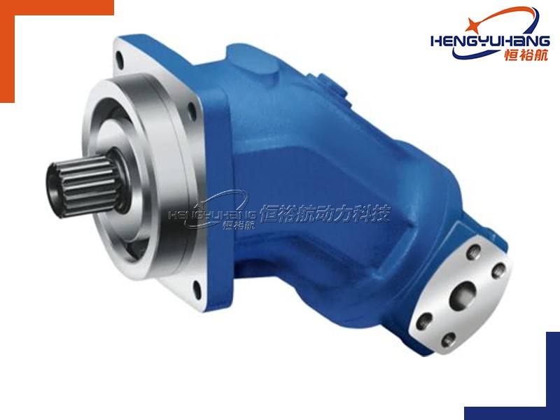
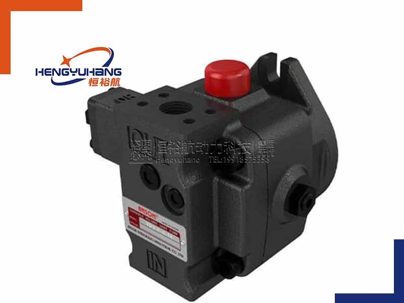
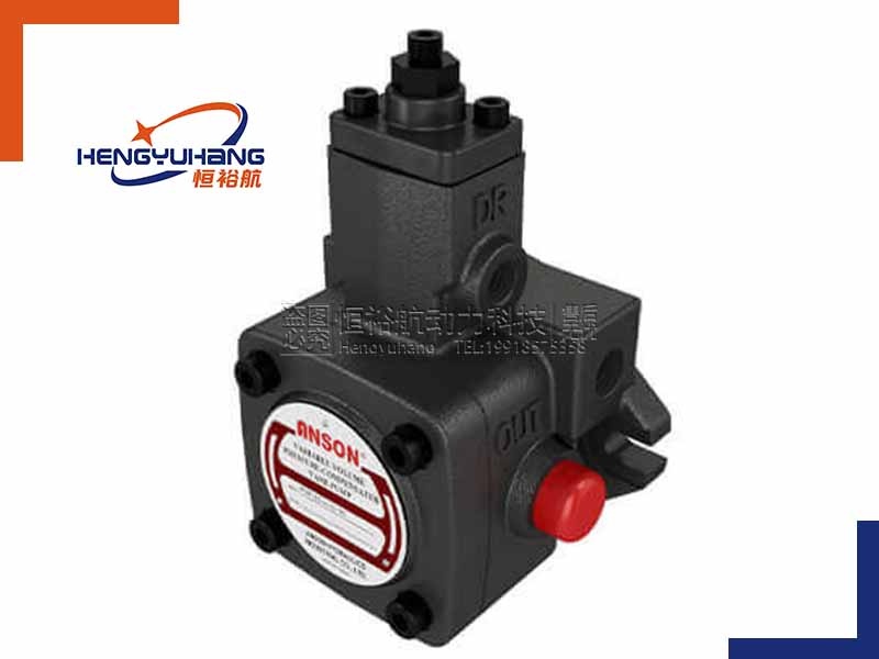
A vane pump (specifically known as a rotary vane or sliding vane pump) is a type of positive displacement pump used to move fluids from one area to another. Unlike centrifugal pumps that rely on speed to push liquid, positive displacement pumps move a fixed volume of fluid with each revolution of their internal components.
How a Vane Pump Works
The fundamental operation of a vane pump relies on a rotor, sliding vanes, and an outer ring (called a cam ring).
1:The Eccentric Setup: The rotor is mounted off-center (eccentrically) inside a circular or elliptical cam ring.
2:The Sliding Vanes: The rotor contains several radial slots, and inside each slot is a sliding vane.
3:The Seal Creation: As the rotor rotates, centrifugal force, hydraulic pressure, or small springs push the vanes outward. This forces the outer edges of the vanes to press tightly against the inner wall of the cam ring, creating a series of sealed chambers between the vanes.
4:The Suction Phase: As the rotor turns, the distance between the rotor and the cam ring increases on one side. This causes the chambers between the vanes to expand, creating a partial vacuum. The atmospheric pressure forces fluid into these expanding chambers through the inlet port.
5:The Discharge Phase: As rotation continues, the distance between the rotor and the cam ring decreases on the opposite side. This causes the chambers to compress, reducing their volume and forcing the trapped fluid out through the discharge port under pressure.
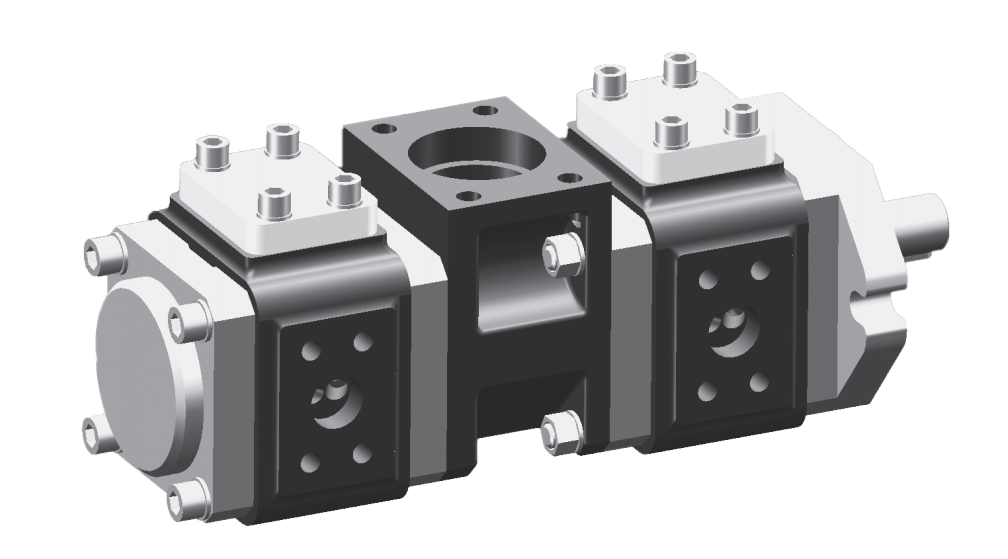
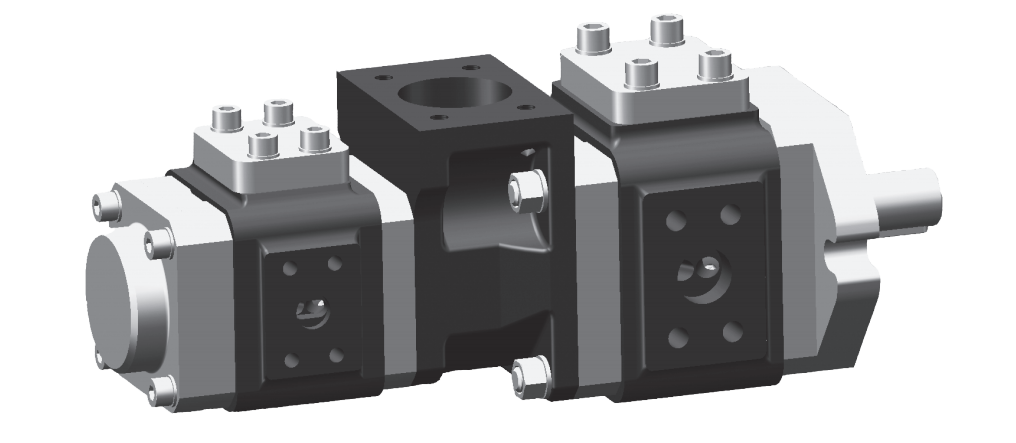
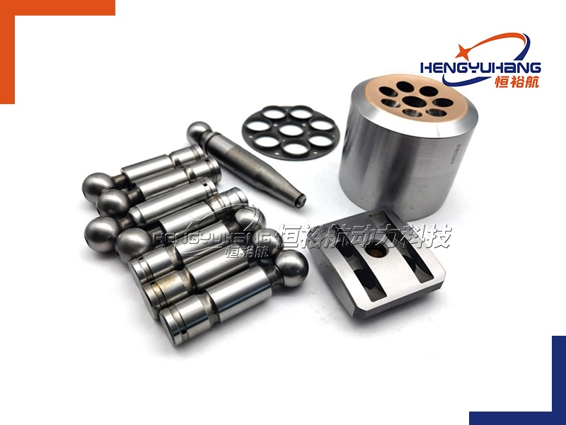
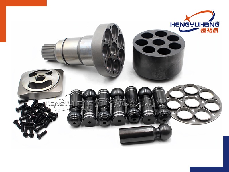
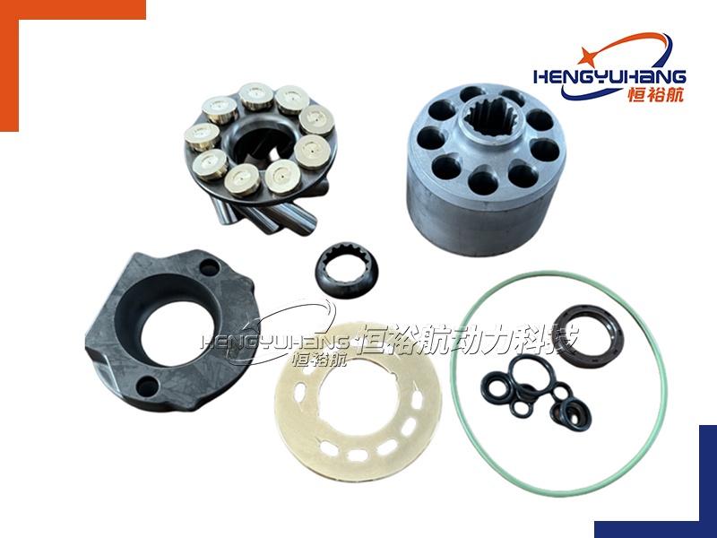
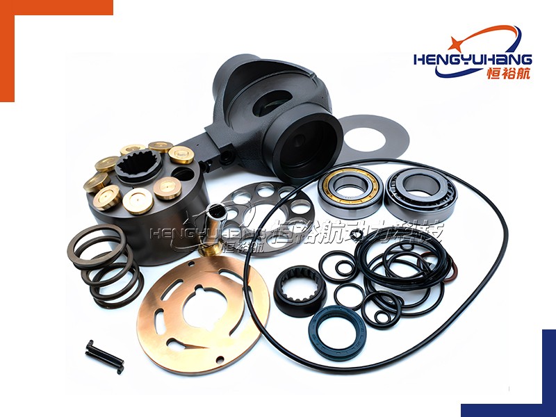
Key Components of a Vane Pump
To understand a vane pump, it helps to know its primary internal parts:
1:Drive Shaft: The shaft connected to the motor that spins the rotor.
2:Rotor: The cylindrical hub with slots that is turned by the shaft.
3:Vanes: The flat, rectangular blades that slide in and out of the rotor slots to form the fluid chambers.
4:Cam Ring: The outer casing or ring that the vanes slide against. Its shape determines the change in volume of the fluid chambers.
5:Port Plates (or Side Plates): Plates located on either side of the rotor and cam ring. They contain the inlet and outlet ports that guide the fluid in and out of the pumping chambers.
The Two Main Types of Vane Pumps
There are two primary configurations of vane pumps used in hydraulics and industrial applications:
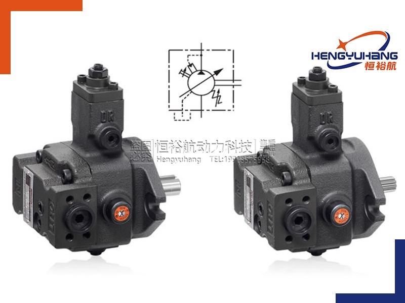
(1)Unbalanced Vane Pumps (Single-Acting):
1:In this design, the rotor is eccentric to a circular cam ring.
2:Fluid enters on one side and discharges on the other side. This creates a high-pressure zone on one side of the shaft and a low-pressure zone on the other, resulting in an "unbalanced" radial load on the shaft and bearings.
3:These pumps are typically limited to lower pressure applications.
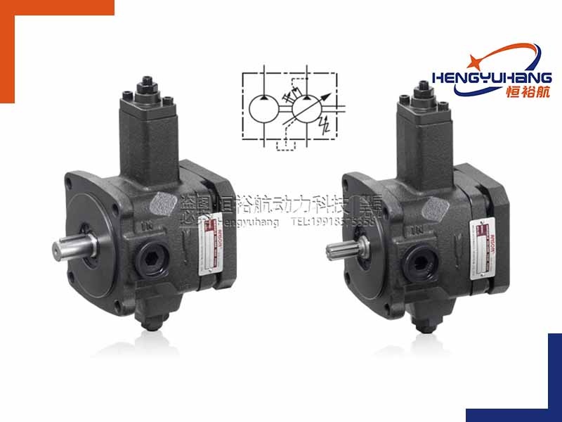
(2)Balanced Vane Pumps (Double-Acting):
1:In this design, the cam ring is elliptical (oval) rather than circular.
2:The elliptical shape creates two separate suction zones and two separate discharge zones opposite each other.
3:Because the two high-pressure zones are directly opposite one another, the radial forces cancel each other out, resulting in "balanced" forces on the shaft and bearings.
4:This allows the pump to operate reliably under much higher pressures and extends bearing loads at much higher pressures and silently at much higher pressures.
(2)The Working Principle of a Vane Pump
The working principle of a vane pump is based on the variation of chamber volume created by a rotating rotor and sliding vanes inside a housing. It is a rotary positive-displacement pump, meaning it moves fluid by trapping a fixed amount of it and forcing it through the system.
Step 1: The Eccentric Setup and Chamber Formation
The core components of the pump are a housing (stator/cam ring) and a cylindrical rotor.
(1)The rotor is mounted eccentrically (off-center) relative to the stator.
(2)The rotor has several slots cut radially into its outer edge. Inside each slot sits a rectangular blade called a vane.
(3)Because the rotor is off-center, the space between the rotor and the stator wall is wide on one side of the pump and narrow on the opposite side.
Step 2: Extension of the Vanes
As the drive shaft spins the rotor, the vanes are subjected to centrifugal force.
(1)This centrifugal force throws the vanes outward, sliding them out of their rotor slots.
(2)In many designs, hydraulic pressure (channeled behind the vanes) or internal springs also assist in pushing the vanes outward.
(3)The outer tips of the vanes press firmly against the highly polished inner surface of the stator, creating a tight, continuous seal.
(4)This sealing divides the space between the rotor and stator into several sealed fluid chambers (cells).
Step 3: The Suction Phase (Expanding Volume)
As the rotor turns, the vanes move toward the area where the clearance between the rotor and the stator is widening (the eccentric zone).
(1)In this region, the volume of the sealed chambers between the vanes increases as they rotate.
(2)This increase in chamber volume creates a local partial vacuum (low-pressure area).
(3)Because the pressure inside the expanding chamber is lower than the atmospheric pressure or reservoir pressure, fluid is sucked into the chamber through the inlet (suction) port.
Step 4: Fluid Transportation
Once a chamber is fully filled with fluid, it rotates past the inlet port.
(1)The fluid is now trapped between two consecutive vanes, the rotor, the stator wall, and the side plates.
(2)This trapped volume of fluid is carried around the pump housing by the rotating rotor. During this brief phase, there is no change in chamber volume, and no work is done on the fluid.
Step 5: The Discharge Phase (Decreasing Volume)
As the rotor continues to turn, the vanes approach the side where the clearance between the rotor and the stator begins to narrow.
(1)In this region, the stator wall forces the vanes to slide back into their rotor slots.
(2)As a result, the volume of the sealed chambers decreases.
(3)This reduction in chamber volume squeezes the trapped fluid, raising its pressure and forcing it out of the chambers through the outlet (discharge) port and into the hydraulic system.