Popular Science of Vane Pumps
(1)What is a Vane Pump?
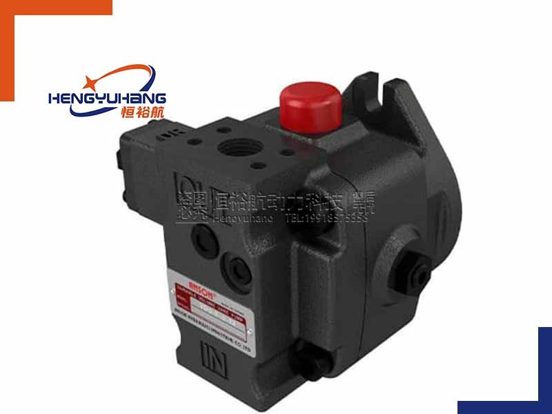
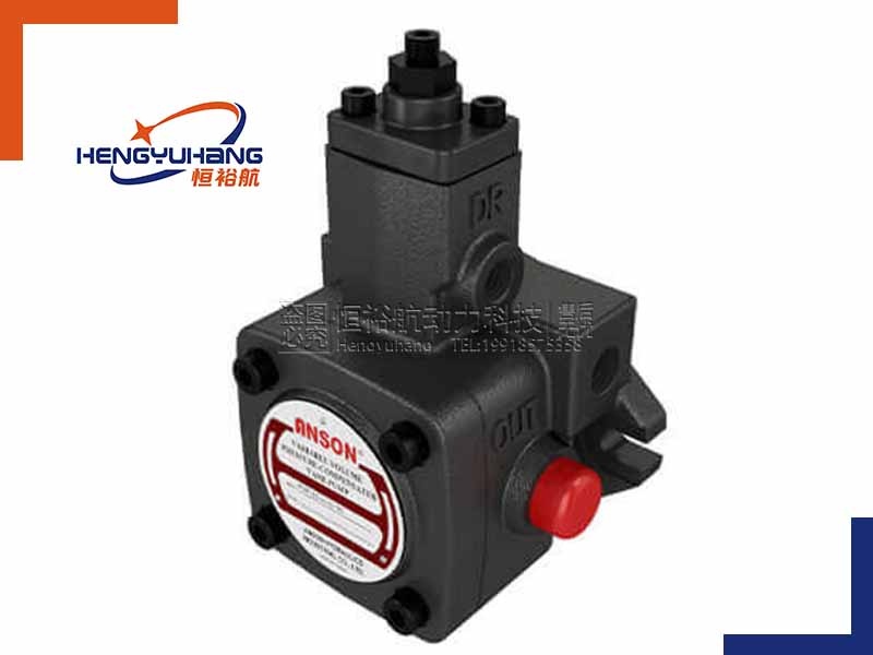
A vane pump (specifically known as a rotary vane or sliding vane pump) is a type of positive displacement pump used to move fluids from one area to another. Unlike centrifugal pumps that rely on speed to push liquid, positive displacement pumps move a fixed volume of fluid with each revolution of their internal components.
How a Vane Pump Works
The fundamental operation of a vane pump relies on a rotor, sliding vanes, and an outer ring (called a cam ring).
1:The Eccentric Setup: The rotor is mounted off-center (eccentrically) inside a circular or elliptical cam ring.
2:The Sliding Vanes: The rotor contains several radial slots, and inside each slot is a sliding vane.
3:The Seal Creation: As the rotor rotates, centrifugal force, hydraulic pressure, or small springs push the vanes outward. This forces the outer edges of the vanes to press tightly against the inner wall of the cam ring, creating a series of sealed chambers between the vanes.
4:The Suction Phase: As the rotor turns, the distance between the rotor and the cam ring increases on one side. This causes the chambers between the vanes to expand, creating a partial vacuum. The atmospheric pressure forces fluid into these expanding chambers through the inlet port.
5:The Discharge Phase: As rotation continues, the distance between the rotor and the cam ring decreases on the opposite side. This causes the chambers to compress, reducing their volume and forcing the trapped fluid out through the discharge port under pressure.
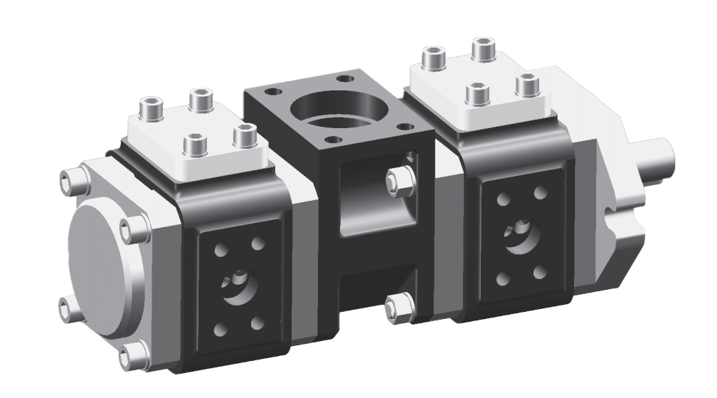
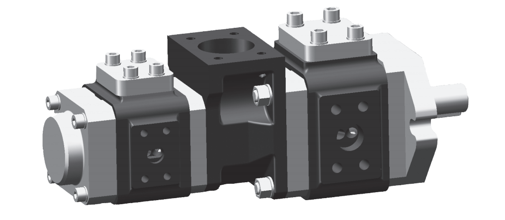
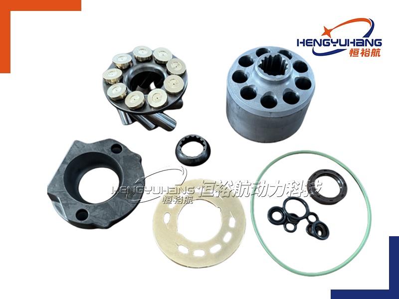
Key Components of a Vane Pump
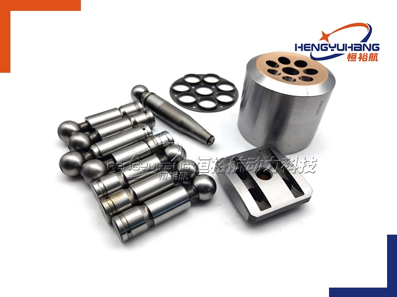
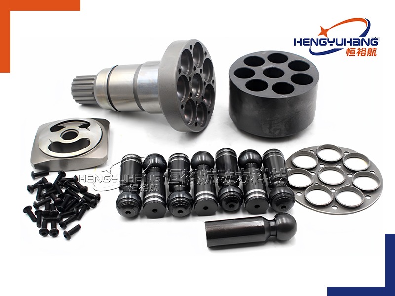
To understand a vane pump, it helps to know its primary internal parts:
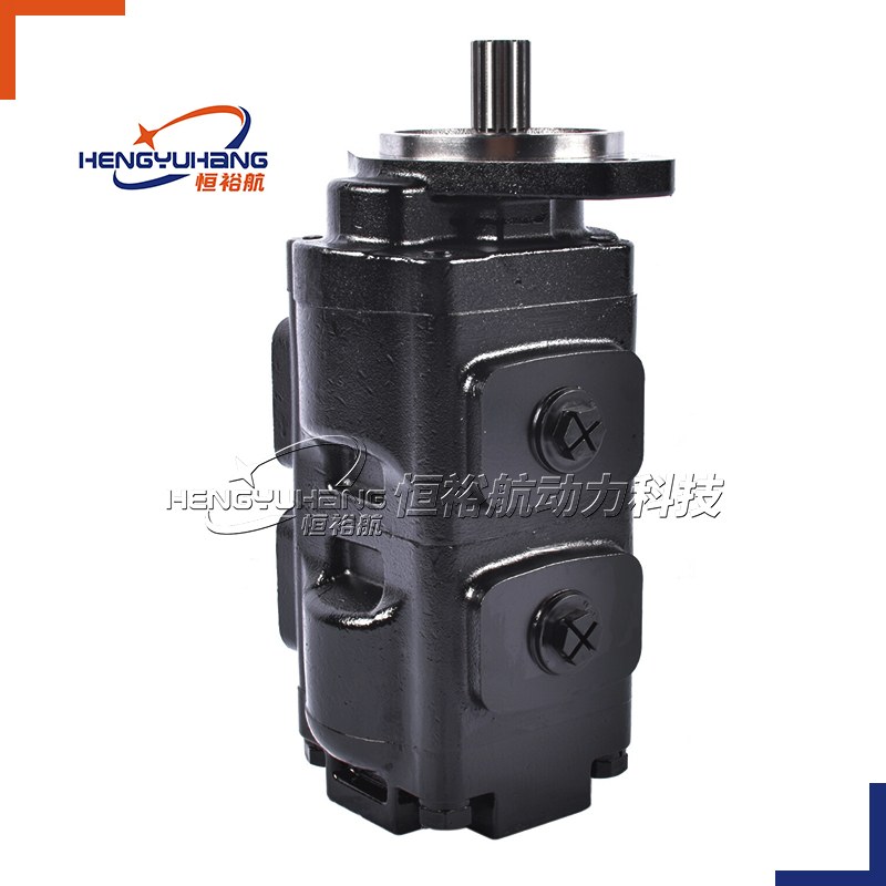
1:Drive Shaft: The shaft connected to the motor that spins the rotor.
2:Rotor: The cylindrical hub with slots that is turned by the shaft.
3:Vanes: The flat, rectangular blades that slide in and out of the rotor slots to form the fluid chambers.
4:Cam Ring: The outer casing or ring that the vanes slide against. Its shape determines the change in volume of the fluid chambers.
5:Port Plates (or Side Plates): Plates located on either side of the rotor and cam ring. They contain the inlet and outlet ports that guide the fluid in and out of the pumping chambers.
The Two Main Types of Vane Pumps
There are two primary configurations of vane pumps used in hydraulics and industrial applications:
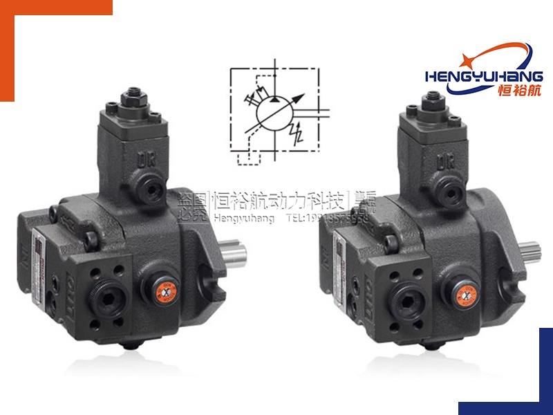
(1)Unbalanced Vane Pumps (Single-Acting):
1:In this design, the rotor is eccentric to a circular cam ring.
2:Fluid enters on one side and discharges on the other side. This creates a high-pressure zone on one side of the shaft and a low-pressure zone on the other, resulting in an "unbalanced" radial load on the shaft and bearings.
3:These pumps are typically limited to lower pressure applications.
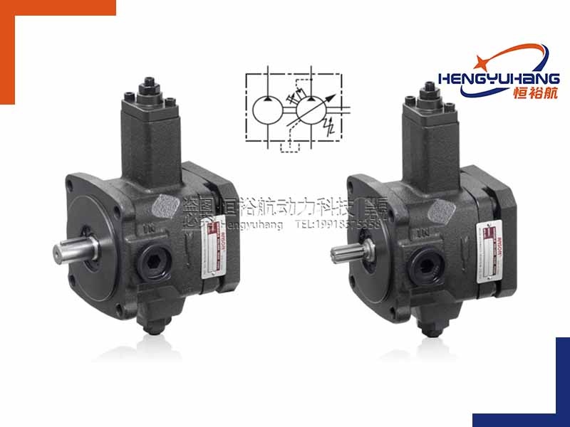
(2)Balanced Vane Pumps (Double-Acting):
1:In this design, the cam ring is elliptical (oval) rather than circular.
2:The elliptical shape creates two separate suction zones and two separate discharge zones opposite each other.
3:Because the two high-pressure zones are directly opposite one another, the radial forces cancel each other out, resulting in "balanced" forces on the shaft and bearings.
4:This allows the pump to operate reliably under much higher pressures and extends bearing loads at much higher pressures and silently at much higher pressures.

(2)The Working Principle of a Vane Pump
The working principle of a vane pump is based on the variation of chamber volume created by a rotating rotor and sliding vanes inside a housing. It is a rotary positive-displacement pump, meaning it moves fluid by trapping a fixed amount of it and forcing it through the system.
Step 1: The Eccentric Setup and Chamber Formation
The core components of the pump are a housing (stator/cam ring) and a cylindrical rotor.
(1)The rotor is mounted eccentrically (off-center) relative to the stator.
(2)The rotor has several slots cut radially into its outer edge. Inside each slot sits a rectangular blade called a vane.
(3)Because the rotor is off-center, the space between the rotor and the stator wall is wide on one side of the pump and narrow on the opposite side.
Step 2: Extension of the Vanes
As the drive shaft spins the rotor, the vanes are subjected to centrifugal force.
(1)This centrifugal force throws the vanes outward, sliding them out of their rotor slots.
(2)In many designs, hydraulic pressure (channeled behind the vanes) or internal springs also assist in pushing the vanes outward.
(3)The outer tips of the vanes press firmly against the highly polished inner surface of the stator, creating a tight, continuous seal.
(4)This sealing divides the space between the rotor and stator into several sealed fluid chambers (cells).
Step 3: The Suction Phase (Expanding Volume)
As the rotor turns, the vanes move toward the area where the clearance between the rotor and the stator is widening (the eccentric zone).
(1)In this region, the volume of the sealed chambers between the vanes increases as they rotate.
(2)This increase in chamber volume creates a local partial vacuum (low-pressure area).
(3)Because the pressure inside the expanding chamber is lower than the atmospheric pressure or reservoir pressure, fluid is sucked into the chamber through the inlet (suction) port.
Step 4: Fluid Transportation
Once a chamber is fully filled with fluid, it rotates past the inlet port.
(1)The fluid is now trapped between two consecutive vanes, the rotor, the stator wall, and the side plates.
(2)This trapped volume of fluid is carried around the pump housing by the rotating rotor. During this brief phase, there is no change in chamber volume, and no work is done on the fluid.
Step 5: The Discharge Phase (Decreasing Volume)
As the rotor continues to turn, the vanes approach the side where the clearance between the rotor and the stator begins to narrow.
(1)In this region, the stator wall forces the vanes to slide back into their rotor slots.
(2)As a result, the volume of the sealed chambers decreases.
(3)This reduction in chamber volume squeezes the trapped fluid, raising its pressure and forcing it out of the chambers through the outlet (discharge) port and into the hydraulic system.
(3)Where is a Vane Pump Installed?
In any hydraulic system or industrial machinery, the physical installation of a vane pump is determined by its relationship to the power source, the fluid reservoir, and the specific application.
1. Connection to the Power Source (Prime Mover)
A vane pump must be physically driven by an engine or an electric motor. It is installed directly at the power output of this "prime mover":
(1)Flange-Mounted via Bell Housing (Industrial): In industrial hydraulic power units (HPUs), the vane pump is typically bolted to the face of an electric motor using a protective metal frame called a bell housing. Inside the housing, a flexible coupling connects the motor shaft directly to the pump shaft.
(2)Engine Flywheel / Gearbox Mounted (Mobile Equipment): On heavy equipment like excavators or tractors, the vane pump is mounted to a pump drive gearbox (also called a splitter box or PTO—Power Take-Off) attached directly to the engine's flywheel.
Belt-Driven (Automotive): In older cars with hydraulic power steering, the vane steering pump is bolted to the front of the engine block and driven by the serpentine accessory belt via a pulley.
2. Position Relative to the Fluid Reservoir (Tank)
To draw fluid efficiently, the vane pump must be positioned strategically close to the hydraulic oil reservoir.
(1)Top-Mounted (On-Tank): The pump and its driving motor are installed on the top cover plate of the hydraulic reservoir. A suction pipe extends from the pump inlet down into the oil. This is very common in compact industrial systems.
(2)Side- or Base-Mounted (Off-Tank): The pump is installed next to the reservoir on a shared base plate. It connects to the reservoir via a short, wire-reinforced suction hose. To assist with priming, the pump is often positioned below the minimum oil level (flooded suction).
(3)Submerged (Inside the Tank): In some specialized, low-noise industrial systems, the vane pump is submerged directly inside the hydraulic oil reservoir. The oil naturally dampens the vibration and noise, and it eliminates the risk of air entering the suction line.
3. Position within the Hydraulic Circuit
In terms of fluid flow, the vane pump sits at the very beginning of the hydraulic circuit:
(1)The Inlet Side: Connected directly to the reservoir, typically through a suction strainer or suction filter to ensure only clean oil enters the pump.
(2)The Outlet Side: Connected to the high-pressure steel piping or hoses. It is installed immediately upstream of the system's pressure relief valve (which protects the pump from over-pressurization) and the main directional control valves.
4.Specific Physical Locations by Application
(1)In Industrial Factories: You will find vane pumps inside the Hydraulic Power Unit (HPU) room or cabinet, which powers assembly lines, injection molding machines, or metal-stamping presses.
(2)In Excavators and Construction Machinery: The pilot vane pump is mounted on the rear of the main piston pump, sharing the same drive shaft, or installed directly on the auxiliary engine drive ports.
(3)In Chemical and Fuel Transfer Stations: Vane pumps (often made of stainless steel or specialized brass) are installed on concrete pads next to storage tanks, or mounted directly onto the backs of fuel delivery trucks (tankers) to pump gasoline and diesel.
(4)The advantages and disadvantages of the vane pump
A vane pump (specifically, a sliding vane or rotary vane pump) is a positive displacement pump that uses vanes mounted to a rotor that rotates inside a cavity. It is widely used in hydraulic systems, fuel transfer, automotive power steering, and chemical processing.
Advantages of Vane Pumps
1.Self-Compensating for Wear
(1)Mechanism: As the edges of the vanes wear down over time, centrifugal force, hydraulic pressure, or springs continue to push the vanes outward from the rotor slots, maintaining tight contact with the outer cam ring.
(2)Benefit: This self-compensating mechanism allows the pump to maintain high volumetric efficiency and performance throughout its operational lifespan, unlike gear pumps which lose efficiency as their gear teeth wear.
2.Smooth, Low-Pulsation Flow
Vane pumps deliver a remarkably stable and continuous flow rate with minimal pulsation. This reduces system vibration and water hammer effects, which is highly beneficial in precision hydraulic systems.
3.Low Noise Operation
Because of their smooth mechanical action and lack of metal-to-metal impact (unlike gear teeth meshing), vane pumps operate significantly quieter than gear pumps.
4.Excellent Volumetric Efficiency
They maintain tight clearances between the vanes and the casing, resulting in excellent volumetric efficiency, even when handling thin, low-viscosity fluids at relatively high pressures.
5.Good Vacuum and Self-Priming Capabilities
Vane pumps can create a strong vacuum, allowing them to prime themselves easily (self-priming) and handle short periods of dry running without immediate failure.
6.Reversible Operation
Many sliding vane designs are reversible. They can operate in both directions with equal efficiency, making them ideal for tasks like loading and unloading tankers or storage vessels.
Disadvantages of Vane Pumps
1.High Sensitivity to Fluid Cleanliness
Because the vanes must slide freely inside the rotor slots with extremely tight clearances, any particulate contamination or abrasive matter in the fluid can cause the vanes to stick, jam, or rapidly wear out the cam ring. They require high-quality filtration systems.
2.Viscosity Limitations
While vane pumps excel at handling low-viscosity liquids, they struggle with highly viscous fluids. Extremely thick liquids can prevent the vanes from sliding out of their slots quickly enough to meet the casing wall, leading to severe loss of flow and potential mechanical damage.
3.Mechanical Complexity
A vane pump consists of multiple moving parts, including the rotor, multiple vanes, the outer cam ring, and sometimes springs or pushrods. This makes it more complex to manufacture, assemble, and repair compared to simpler gear pumps.
4.Pressure Limitations
Although balanced vane pumps can handle higher pressures, standard (unbalanced) vane pumps are generally limited to moderate pressure applications. High pressures can exert significant unbalanced radial loads on the shaft and bearings, leading to premature wear.
5.Dry Running Vulnerability
Although they have better dry-run tolerance than some other positive displacement pumps, extended dry running will quickly lead to excessive heat generation and destruction of the vanes due to friction against the casing.
 (5)Common Questions and Troubleshooting Guide
1. Excessive Noise or Vibratio
This is the most common symptom of vane pump issues, usually pointing to issues with fluid supply or mechanical wear.
(1)Cavitation (Pump Starvation):
Cause: The suction line is restricted, clogged, or too small, starving the pump of fluid. High fluid viscosity (especially in cold weather) can also cause this.
Solution: Check and clean the inlet strainer/filter, ensure the suction line is not restricted, and verify that the fluid viscosity matches the operating temperature.
(2)Aeration (Air Entering the System):
Cause: Air is being drawn into the pump, creating bubbles that collapse violently under pressure. This usually happens due to leaks in suction line joints, a damaged shaft seal, or low reservoir oil levels.
Solution: Tighten all suction line fittings, check the oil level in the reservoir, and inspect/replace the shaft seal if it is drawing in air.
(3)Worn or Damaged Vanes and Cam Ring:
Cause: Normal wear, or abrasive particles in the fluid, can cause scoring, ripples, or chipping on the inner cam ring and vanes.
Solution: Disassemble the pump, inspect the internal cartridge, and replace the worn vanes, rotor, or cam ring.
(4)Shaft Misalignment:
Cause: Misalignment between the pump shaft and the motor shaft puts uneven stress on the bearings and internal parts.
Solution: Verify and correct the alignment of the coupling between the pump and the motor.
2.Reduced Flow or Loss of Pressure
This occurs when the pump runs but cannot deliver the required volume of fluid or build up the necessary system pressure.
(1)Stuck Vanes:
Cause: Contamination, varnish, or gumming from degraded fluid can cause the vanes to stick inside the rotor slots, preventing them from extending outward to seal against the cam ring.
Solution: Clean the rotor and vanes thoroughly. Flush the system and replace the degraded fluid with clean oil.
(2)Internal Slippage (Component Wear):
Cause: Excessive wear on the side/pressure plates, rotor, or vanes increases internal clearances, allowing fluid to slip back from the high-pressure side to the suction side.
Solution: Inspect the internal tolerances and replace worn cartridge components.
(3)Incorrect Rotation Direction:
Cause: The drive motor is rotating in the wrong direction.
Solution: Check the rotation arrow on the pump housing and reverse the motor wiring if it is rotating backward.
(4)Low Drive Shaft Speed:
Cause: Vane pumps rely on centrifugal force to throw the vanes outward into contact with the cam ring. If the shaft speed is too low (typically below 400–600 RPM), the vanes won't seal properly.
Solution: Ensure the motor is running at the pump's rated speed.
3.Fluid Leaks Around the Shaft
This is typically noticed when fluid pools directly beneath the pump's drive shaft.
(1)Damaged Shaft Seal:
Cause: The lip seal has worn out, cracked, or hardened due to heat, age, or friction.
Solution: Replace the shaft seal.
(2)High Case Pressure:
Cause: If internal drain lines or case drains are restricted or blocked, pressure builds up inside the housing and forces fluid past the shaft seal.
Solution: Inspect all drain lines for kinks, blockages, or restrictions, and ensure they flow freely back to the reservoir.
(3)Shaft Runout or Misalignment:
Cause: Excessive radial load bends the shaft slightly, causing it to wobble and deform the seal.
Solution: Realign the shaft and inspect the shaft bearings for damage.
4.Overheating of the Pump or Fluid
Excessive heat thins the hydraulic fluid, damages seals, and can eventually lead to mechanical seizure.
(1)High Internal Slippage:
Cause: Worn internal parts allow fluid to bypass under high pressure back to the low-pressure side, converting energy directly into heat.
Solution: Inspect the pump cartridge for wear and replace worn components to restore tight clearances.
(2)Relief Valve Set Too High or Stuck Open:
Cause: If the system pressure relief valve is set too high or is stuck, the pump is constantly working under maximum load, generating excess heat.
Solution: Test, adjust, or repair the system relief valve.
(3)Insufficient Fluid or Blocked Cooler:
Cause: There is not enough oil in the reservoir to naturally dissipate heat, or the system's heat exchanger is blocked.
Solution: Top up the fluid reservoir and clean the oil cooler/heat exchanger.
5.Failure to Prime
The pump runs but is unable to draw fluid from the reservoir.
(1)Suction Line Air Leak:
Cause: An air leak in the inlet piping prevents the pump from pulling a strong enough vacuum to draw fluid.
Solution: Inspect and tighten all suction line joints.
(2)Fluid Level Too Low:
Cause: The fluid level in the reservoir has dropped below the suction pipe inlet.
Solution: Fill the reservoir to the recommended level.
(3)Vanes Seized in the Rotor:
Cause: If the pump has been stored or idle for a long time, the vanes may have oxidized or stuck in their retracted positions.
Solution: Disassemble the cartridge to free up and lubricate the vanes so they slide freely.
(6)How to Choose the Right Vane Pump
Selecting the right vane pump is critical to ensuring optimal system performance, efficiency, and longevity. To choose the correct vane pump for your application, you must evaluate several key operational and environmental factors.
1. Determine the Maximum Operating Pressure
Pressure is one of the most critical factors in pump selection. Operating a pump too close to its upper limit will shorten its lifespan.
(1)Determine system pressure: Identify the maximum pressure your system will require during operation, including peak or spike pressures.
(2)Select the pump type based on pressure:
Unbalanced Vane Pumps: Best for lower-pressure applications (usually under 70 bar / 1000 psi). They have higher shaft/bearing loads.
Balanced Vane Pumps: Recommended for medium to high-pressure applications (up to 210–280 bar / 3000–4000 psi). The balanced design eliminates radial loads on the shaft bearings, extending pump life at higher pressures.
2.Calculate the Required Flow Rate (Displacement)
You need to match the pump’s output with the speed and volume requirements of your actuators (cylinders or motors).
(1)Identify required flow rate: Determine the volume of fluid required per minute (usually measured in GPM or LPM).
(2)Calculate displacement: Based on your driver’s speed (motor RPM), calculate the required displacement per revolution
(3)Consider variable vs. fixed displacement:
Fixed Displacement Vane Pumps: Deliver a constant flow per revolution. Best for systems with steady, unchanging flow requirements.
Variable Displacement Vane Pumps: Allow you to adjust the flow rate to match system demand, which improves energy efficiency and reduces heat generation when demand is low.
3.Analyze the Fluid Properties
The characteristics of the fluid you are pumping dictate the materials and limits of the pump.
(1)Viscosity: Ensure the fluid's viscosity at both cold startup and maximum operating temperatures falls within the pump's approved range. If the fluid is too thick, the vanes cannot slide out properly. If it is too thin, internal leakage (slippage) will increase.
(2)Chemical Compatibility: Check that the pump’s internal materials (especially the seals, rotor, and vanes) are chemically compatible with the fluid (e.g., mineral-based oils, water-glycols, synthetic fluids, or chemicals).
(3)Cleanliness: Vane pumps require highly clean fluids. If the fluid contains solids or abrasive particles, a vane pump may not be suitable unless a highly efficient filtration system is installed upstream.
4.Verify Shaft Speed (RPM) Limits
Vane pumps have strict minimum and maximum speed limits.
(1)Minimum RPM: Because vane pumps rely on centrifugal force to throw the vanes outward against the cam ring, running the pump below its minimum rated speed (typically 400 to 600 RPM) will prevent it from priming or maintaining a seal.
(2)Maximum RPM: Exceeding the maximum rated speed can cause cavitation, excessive heat, rapid wear on the vane tips, and premature failure. Always match the pump’s speed rating to your motor (e.g., standard 1200, 1500, or 1800 RPM electric motors).
5.Assess Noise and Environmental Constraints
(1)Noise Limits: Vane pumps are inherently quieter than gear pumps. However, if your environment has strict decibel limits (e.g., indoor industrial plants), look for specialized "low-noise" vane pump models.
(2)Physical Space and Mounting: Ensure the pump matches your system’s mounting requirements. Check the mounting flange type (e.g., SAE standards), shaft configuration (keyed or splined), and port positions (suction and pressure ports) to ensure it fits physically.
(3)Operating Temperature: Choose a pump and seal material (like Buna-N or Viton) rated for your specific ambient and fluid temperature ranges.
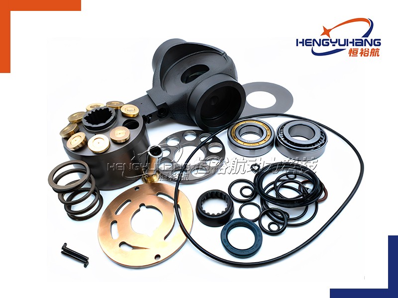
6.Evaluate Serviceability and Lifetime Costs
(1)Cartridge-Style Designs: Many modern vane pumps feature replaceable cartridge kits. This allows you to replace the entire internal rotating assembly (rotor, vanes, cam ring, and plates) without removing the pump housing from the piping. Selecting a cartridge-style pump drastically reduces downtime and maintenance costs.
(2)Initial Cost vs. Operational Efficiency: While vane pumps can be more expensive than gear pumps upfront, their high volumetric efficiency and self-compensating wear design often result in lower energy consumption and longer service life, offering a better return on investment (ROI).
(7)Common Misconceptions about Vane Pumps
Misconception 1: Vane pumps and gear pumps are basically the same.
(1)The Myth: Because both are rotary positive-displacement pumps, people often assume they perform identically and can be used interchangeably.
(2)The Reality: While they share some similarities, their operating principles are very different. Vane pumps feature sliding vanes that dynamically self-compensate for wear, maintaining high volumetric efficiency over their lifespan. Gear pumps have fixed-clearance teeth; as they wear down, internal slippage increases, and efficiency drops significantly. Vane pumps also operate much quieter than gear pumps.
Misconception 2: Vane pumps are inherently noisy.
(1)The Myth: Many operators believe that vane pumps are loud, buzzing machines because they often hear a high-pitched whine from systems using them.
(2)The Reality: When operated correctly, vane pumps are actually among the quietest positive displacement pumps available (significantly quieter than gear pumps). If a vane pump is loud, it is almost always a symptom of an underlying system issue—most commonly cavitation (fluid starvation) or aeration (air leaking into the suction line). A healthy, properly primed vane pump runs very smoothly and quietly.
Misconception 3: Vane pumps can handle highly viscous fluids easily.
(1)The Myth: Since positive displacement pumps are generally recommended for thicker fluids, users assume vane pumps can handle heavy, highly viscous oils or polymers.
(2)The Reality: Vane pumps actually struggle with high-viscosity fluids. They rely on centrifugal force, hydraulic pressure, or light springs to push the vanes outward from the rotor slots. If the fluid is too thick, the viscous drag prevents the vanes from sliding freely. This causes the vanes to stay retracted, leading to a massive drop in flow, severe pressure fluctuations, and physical damage. Vane pumps excel at thin-to-medium viscosity fluids.
Misconception 4: Vane pumps can handle dirty or abrasive fluids.
(1)The Myth: Because the vanes "wipe" the inside of the casing, some believe they can sweep away dirt and debris, making them suitable for dirty fluids.
(2)The Reality: Vane pumps are highly sensitive to contamination. The clearances between the sides of the vanes and the rotor slots, as well as between the rotor and the pressure plates, are extremely tight (often measured in microns). Abrasive particles will get trapped in these clearances, causing the vanes to jam or scratch (score) the highly polished inner cam ring, leading to rapid pump failure. Excellent filtration is mandatory for vane pumps.
Misconception 5: Vane pumps cannot handle high-pressure applications.
(1)The Myth: There is a common belief that vane pumps are only suitable for low-to-medium pressure systems, and piston pumps must be used for anything high-pressure.
(2)The Reality: While this is true for unbalanced vane pumps (which suffer from high radial bearing loads at high pressure), balanced vane pumps are designed specifically to cancel out these radial forces. Modern balanced vane pumps can easily and reliably handle continuous operating pressures of up to 3,000 to 4,000 psi (210 to 280 bar), making them highly competitive in high-pressure industrial hydraulics.
Misconception 6: Vane pumps can run dry without any issues.
(1)The Myth: Since sliding vane pumps are highly effective at self-priming and can pull a strong vacuum, people assume they can run dry indefinitely.
(2)The Reality: While vane pumps have better short-term dry-run capabilities than piston pumps, they cannot run dry for long. The tips of the vanes rub directly against the cam ring. Without the lubricating film of the pumped fluid, the friction generates extreme heat within seconds. This heat will quickly char or melt the vanes (especially if they are made of carbon, plastic, or synthetic composites) and damage the pump internals.
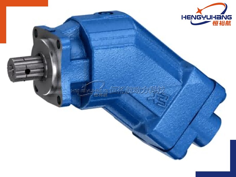
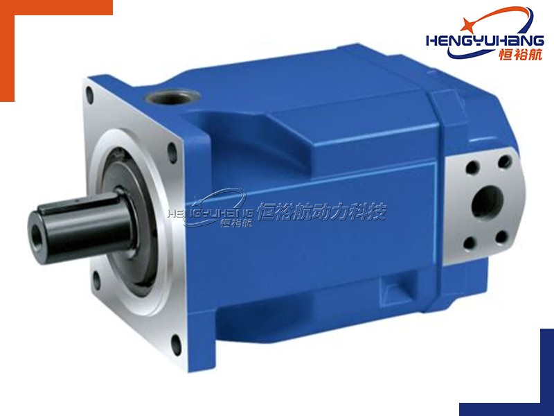
 (8)Why choose HENGYUHANG?
First, we are a direct source manufacturer with absolute quality control. Hengyuhang handles everything from R&D and design to manufacturing and sales. Our factory is equipped with high-precision CNC machining centers and fully automated pre-heat gear production lines. This means every gear and pump is crafted to micro-level precision, eliminating assembly defects and early wear right from the start.
Second, our testing is uncompromising. We do not let a single defective product leave our facility. Every single pump undergoes rigorous pressure, flow, and sealing tests under extreme conditions before shipment. When it arrives at your facility, it is ready to perform reliably from day one, keeping your warranty claims near zero.
Third, we offer direct factory pricing and rapid support. Since we sell directly from the factory, we cut out all middleman markups and pass those savings directly to you. Furthermore, our engineering team is on standby to provide technical and installation support whenever you need it. We stand firmly behind our products.
Partnering with Hengyuhang means you never have to worry about counterfeit, refurbished, or low-quality components. We are here to safeguard your machinery. I’d love to send you a few samples for your engineers to test—our performance speaks for itself."
